
Article Transport Facility

a technology for transporting facilities and articles, applied in the direction of transportation and packaging, railway vehicles, electric vehicles, etc., can solve the problems of increasing the size of the increasing the number of restrictions regarding the arrangement, and increasing so as to facilitate the expansion of the facility in the second direction, reduce the size of the facility, and simplify the effect of the facility

Active Publication Date: 2018-03-15
DAIFUKU CO LTD
View PDF4 Cites 3 Cited by
  • Summary
  • Abstract
  • Description
  • Claims
  • Application Information

AI Technical Summary

Benefits of technology

The patent describes a way to arrange two cable bodies in a transport facility, which helps to reduce the size and complexity of the facility. By arranging the cable bodies on the same side of the rail, their arrangement spaces can be combined, and other members can be arranged more flexibly. This results in a smaller facility and simpler arrangement of other members. Overall, this configuration allows for a more efficient and simplified article transport facility.

Problems solved by technology

As a result, the facility is likely to increase in size in the second direction.
In addition, since the cable body arrangement spaces are present on both sides in the second direction relative to the rail, the number of restrictions is likely to increase regarding the arrangement of other members that are arranged near the floor similarly to the cable bodies.
This may also lead to an increase in the size of the facility.
In the case of applying a complex arrangement to avoid the cable body arrangement spaces to the other members, there is also concern of an increase in the complexity of the facility.
However, these points have not been particularly recognized in Patent Document 1.

Method used


Image

  • Article Transport Facility
  • Article Transport Facility
  • Article Transport Facility

Examples


Embodiment Construction

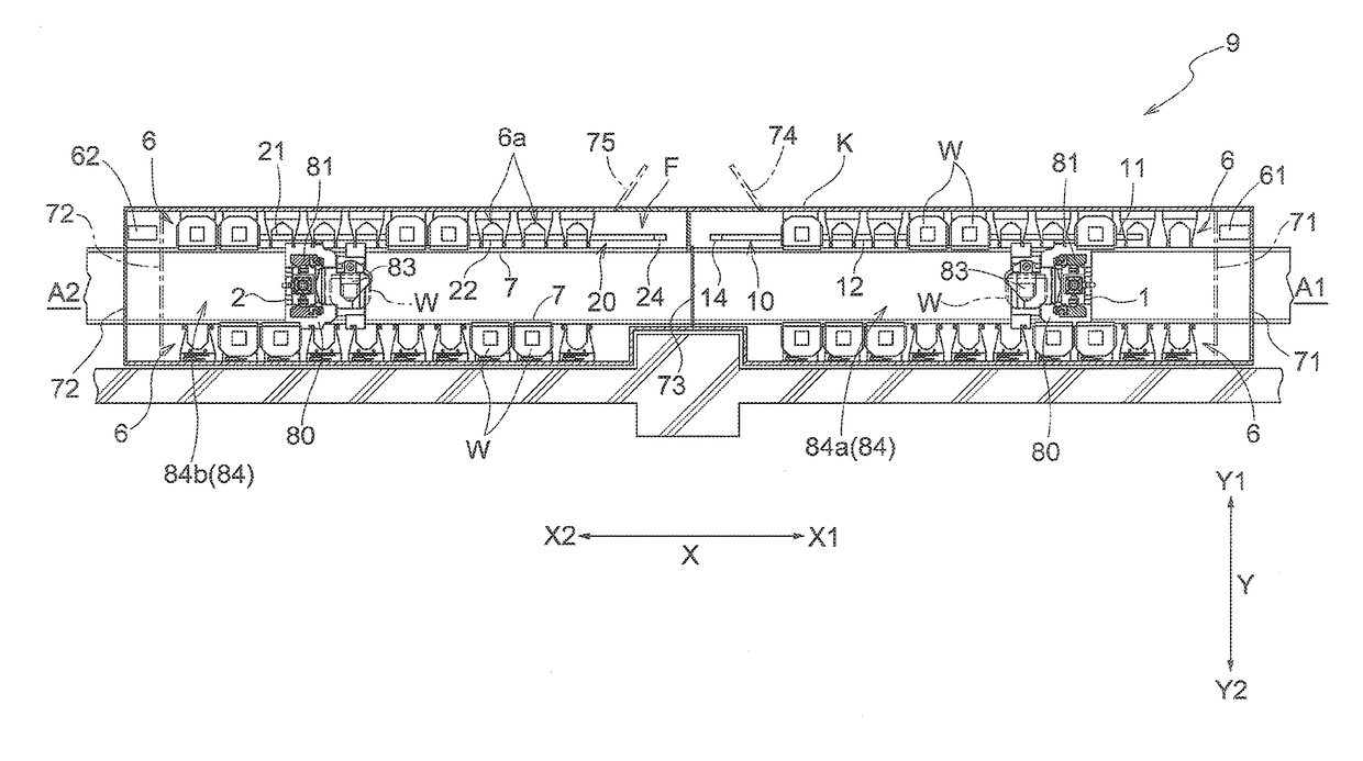
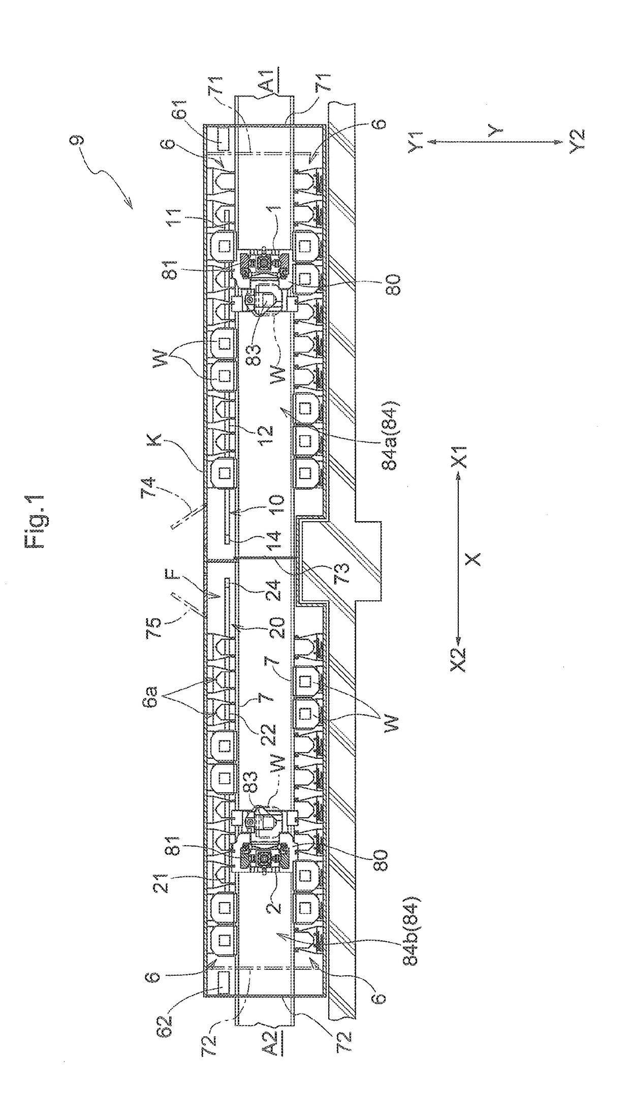
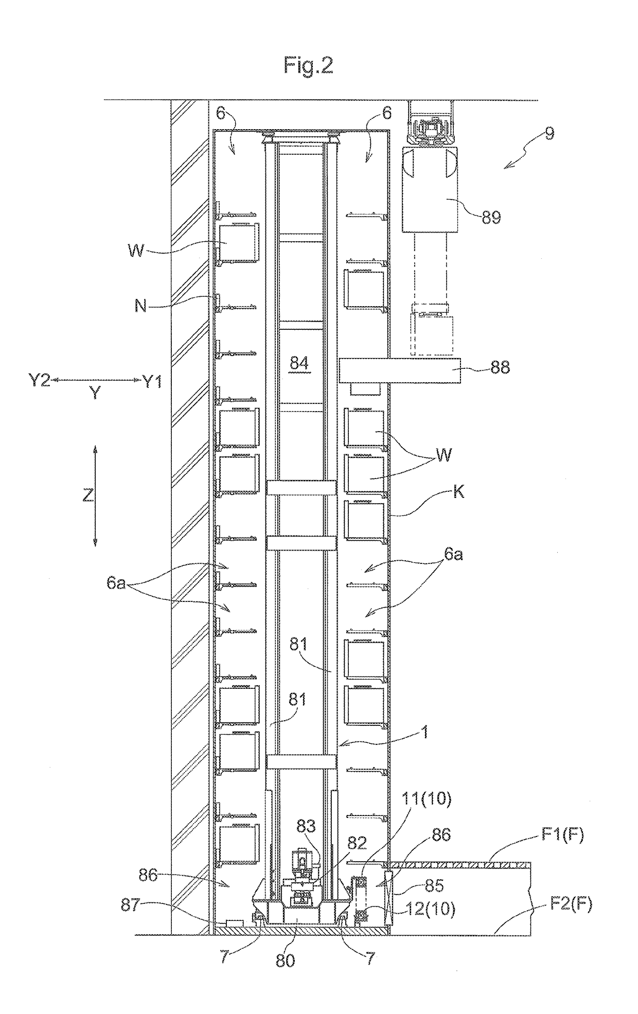
[0024]An embodiment of an article transport facility will be described with reference to the drawings. As shown in FIGS. 1 and 2, an article transport facility 9 includes storage racks 6, a first transport apparatus 1, a second transport apparatus 2, a first cable body 10, and a second cable body 20. In the storage racks 6, a plurality of storage sections 6a for storing articles W are arranged in a first direction X along a horizontal direction. The first transport apparatus 1 and the second transport apparatus 2 move along the first direction X in front of the storage racks 6, and transport articles W to the storage sections 6a or from the storage sections 6a. Rails 7 are installed along the first direction X on a floor F, on which the article transport facility 9 is installed. The first transport apparatus 1 and the second transport apparatus 2 are guided by the rails 7 to move along the first direction X. Assuming that a space in which at least one of the first transport apparatu...


PUM


Abstract

A first cable body allows a first transport apparatus to move in a first movement area by deforming as the first transport apparatus moves along a first direction. A second cable body allows a second transport apparatus to move in a second movement area, which at least partially overlaps the first movement area, by deforming as the second transport apparatus moves along the first direction. Assuming that a direction perpendicular to both the first direction and an up-down direction is a second direction, the first cable body and the second cable body are arranged on the same side in the second direction relative to a rail so that the respective arrangement areas in the second direction overlap each other at least partially.

Description

CROSS-REFERENCE TO RELATED APPLICATION[0001]This application claims priority to Japanese Patent Application No. 2016-176973 filed Sep. 9, 2016, the disclosure of which is hereby incorporated in its entirety by reference.BACKGROUND OF THE INVENTION1. Field of the Invention[0002]The present invention relates to an article transport facility that includes a first transport apparatus and a second transport apparatus that are guided by a rail to move in front of a storage rack, a first cable body for power supply or communication that is connected to the first transport apparatus, and a second cable body for power supply or communication that is connected to the second transport apparatus.2. Description of the Related Art[0003]An article transport facility described in WO 2014 / 125727A (Patent Document 1) is known as the aforementioned article transport facility. Specifically, the article transport facility described in Patent Document 1 includes a first transport vehicle (4) and a second...

Claims


Application Information

Patent Timeline
Patent Type & Authority Applications(United States)
IPC IPC(8): B65G1/04B60L9/00
CPCB65G1/0492B65G1/0407B60L9/00H01L21/00B60L2200/26H01L21/6773H01L21/67706H01L21/67754
Inventor ABE, TAKESHIOMORI, KAZUYA
Owner DAIFUKU CO LTD
Learn More