
Reciprocating piston pump and method of manufacture

a piston pump and reciprocating technology, applied in the field of reciprocating piston pumps, can solve the problems of reducing the contact angle of the piston pump, reducing the contact angle, and reducing the buildup behind the second seal. , the effect of increasing the contact angl

Inactive Publication Date: 2018-03-15
BIO CHEM FLUIDICS INC
View PDF7 Cites 4 Cited by
  • Summary
  • Abstract
  • Description
  • Claims
  • Application Information

AI Technical Summary

Benefits of technology

The patent is about a new design for a piston pump that prevents the buildup of salt and other precipitates that can damage the pump's seal and decrease its lifespan. The design uses hydrophobic pistons that have high contact angles and low surface energy, which makes them less wettable than liquid. This prevents liquids from adhering to the piston and allows them to move away from the seal area, reducing the formation of crystals and other harmful substances. The piston pump also includes a partially fluorinated polymer piston and a drive assembly that interfaces with the piston over a full stroke length. This new design provides better performance and longer lifespan for piston pumps in concentrated salt solutions.

Problems solved by technology

Crystallization will cause rapid degradation of the pump seal as the piston reciprocates.
As salt builds up and adheres to the surface of the piston, either mechanically or chemically binding to the piston, it may abrade the seal, causing leakage.
This creates a piston pump design that is more complex and costly.

Method used


Image

  • Reciprocating piston pump and method of manufacture
  • Reciprocating piston pump and method of manufacture
  • Reciprocating piston pump and method of manufacture

Examples


Embodiment Construction

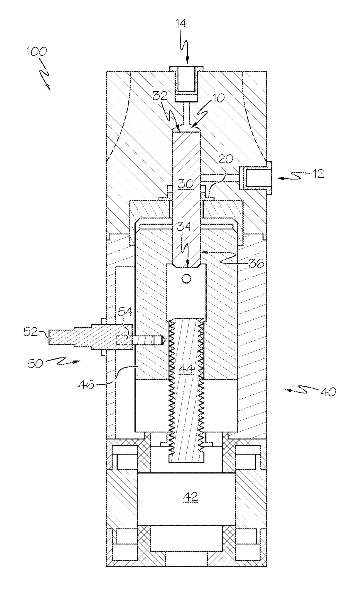
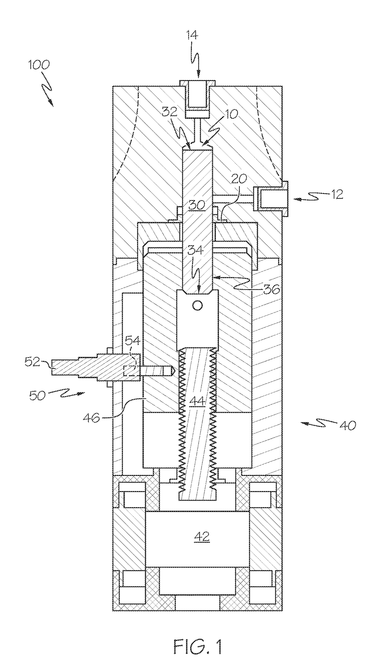
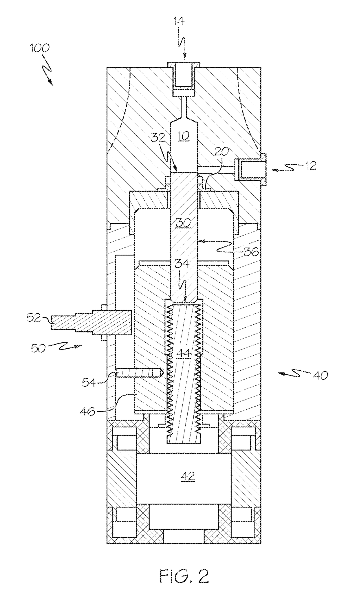
[0016]Referring initially to FIGS. 1 and 2, a reciprocating piston pump 100 is shown. The reciprocating piston pump 100 comprises a pump chamber 10, a piston seal 20, a hydrophobic piston 30 comprising a fluid engaging end 32, a seating end 34, and a longitudinal outer piston surface 36 extending between the fluid engaging end 32 and the seating end 34. The reciprocating piston pump 100 further includes a drive assembly 40 coupled to the seating end 34 of the hydrophobic piston 30.

[0017]As shown in FIGS. 1 and 2, respectively, the drive assembly 40 operates to reciprocate the hydrophobic piston 30 within the pump chamber 10 between full aspirate and full dispense positions. Additionally, the piston seal 20 forms an interface between the longitudinal outer piston surface 36 of the hydrophobic piston 30 and the pump chamber 10. Also, the hydrophobic piston 30 and the drive assembly 40 are configured such that the piston seal 20 interfaces with the longitudinal outer piston surface 36 ...


PUM

PropertyMeasurementUnit
contact angleaaaaaaaaaa
thickaaaaaaaaaa

Abstract

A reciprocating piston pump may include a pump chamber, a piston seal, a monolithic partially fluorinated polymer piston with a fluid engaging end, a seating end, and a longitudinal outer piston surface extending between the fluid engaging end and the seating end. The reciprocating piston pump may further include a drive assembly coupled to the seating end of the monolithic partially fluorinated polymer piston. The drive assembly operates to reciprocate the monolithic partially fluorinated polymer piston within the pump chamber between full aspirate and full dispense positions. The piston seal forms an interface between the longitudinal outer piston surface of the piston and the pump chamber. The monolithic partially fluorinated polymer piston and the drive assembly are configured such that the piston seal interfaces with the longitudinal outer piston surface over a full stroke length of the drive assembly between the full aspirate and full dispense positions.

Description

CROSS-REFERENCE TO RELATED APPLICATIONS[0001]This application claims the benefit of U.S. Provisional Application Ser. No. 62 / 385,662 (BCF 0006 MA), filed Sep. 9, 2016 and U.S. Provisional Application Ser. No. 62 / 406,982 (BCF 0006 M2), filed Oct. 12, 2016.BACKGROUND[0002]The present disclosure relates to piston pumps, which may also be referred to as positive displacement pumps and, more particularly, to improvements in the design and method of manufacture of the piston utilized in the pump.BRIEF SUMMARY[0003]Reciprocating piston pumps may be used to motivate fluids. Generally, fluid is drawn into a sealed chamber through one or more valves by creating a negative difference in pressure between the chamber and the fluid reservoir across the valve(s). This pressure difference may be created using a reciprocating piston to change the volume within the sealed chamber. The fluid that enters the chamber may interact with the piston. Fluid will evaporate from the piston surface(s) behind th...

Claims


Application Information

Patent Timeline
Patent Type & Authority Applications(United States)
IPC IPC(8): F04B53/14
CPCF04B53/143F05C2225/04C09D5/1681C09D127/18F05C2231/00C09D127/12F04B9/02F04B15/04F04B17/03F04B53/02F04B53/14F04B13/00F05C2253/12
Inventor HUANG, HENRYBULUGIOIU, RAZVANEASTERBROOK, WILLIAM
Owner BIO CHEM FLUIDICS INC
Learn More