Automatic transmission control device and control method

a technology of automatic transmission and control device, which is applied in the direction of gearing control, gearing elements, gearing, etc., can solve the problems of judder vibration, inability to achieve smooth shift, so as to reduce friction, increase the effect of rate and smooth locking up

Active Publication Date: 2018-03-15
JATCO LTD +1
View PDF3 Cites 3 Cited by
  • Summary
  • Abstract
  • Description
  • Claims
  • Application Information

AI Technical Summary

Benefits of technology

[0015](5) It is preferable that the control means is configured to perform the first engagement control or the second engagement control; and when the rotation speed difference becomes equal to or smaller than a third predetermined value smaller than a second predetermined value, the control means is configured to increase an increase rate of the increased torque transmission rate, so that rotation speed difference between the input and output elements of the lockup clutch is not decreased even when an output of the internal combustion engine becomes maximum.
[0016]When the output torque of the internal combustion engine is increased in a state where the rotation speed difference between the input and output elements of the lockup clutch is closer to each other after the rotation of the internal combustion engine is increased (sudden increase) when it is shifted again from the engagement state to the full engagement state by the temporal release of the full engagement by the ON operation of the accelerator from the full engagement state of the lockup clutch at the deceleration of the vehicle, the vibration (the judder vibration) may be generated by the variation of the frictional state (the increase and the decrease of the frictional force) between the input and output elements. In the present invention, the predetermined capacity is added to the torque transmission capacity of the lockup clutch. Accordingly, the variation of the frictional state is suppressed to avoid the generation of the judder. The lockup clutch is smoothly locked up.
[0017]Moreover, when the output torque is increased in a state where the rotation of the internal combustion engine is sufficiently increased, that is, in a state where the rotation speed difference between the input and output elements of the lockup clutch does not become large to be closer to each other in a case where the rotation of the internal combustion engine is increased by providing the rotation speed difference between the input and output elements of the lockup clutch by the slip engagement by the first engagement control, the vibration (the judder) may be generated by the variation of the frictional state (the increase and the decrease of the frictional force) between the input and output elements. In this case, the predetermined capacity is also added to the torque capacity of the lockup clutch. Accordingly, the variation of the frictional state is suppressed to avoid the generation of the judder. The lockup clutch is smoothly locked up.
[0018]Moreover, the predetermined capacity is set in accordance with the increase state of the internal combustion engine. It is possible to more surely dissolve the variation of the frictional state, and to smoothly lock up the lockup clutch.

Problems solved by technology

For example, when the engine torque is increased by an additional depression of the accelerator pedal at a timing at which the rotation speed difference becomes small immediately before the full engagement of the lockup clutch, the transmission torque capacity of the lockup clutch with respect to the engine torque is deficient.
With this, it is not possible to attain the smooth shift to the full engagement to cause the judder vibration.

Method used


Image

  • Automatic transmission control device and control method
  • Automatic transmission control device and control method
  • Automatic transmission control device and control method

Examples


Embodiment Construction

[0026]Hereinafter, an embodiment according to the present invention is explained. Besides, the embodiment described below is merely example. There is no intention to exclude application of various variations and arts which are not described in following embodiment.

[0027][1. Configuration]

[0028]Hereinafter, configurations of a driving system and a control system of a vehicle to which a control device for an automatic transmission according to the embodiment explained are explained. Besides, in this embodiment, an automatic transmission is a belt type continuously variable transmission (hereafter, referred to also as a belt CVT or CVT) including a belt type continuously variable transmission mechanism (hereinafter, referred to also as a variator) which is a transmission mechanism. The transmission mechanism can be other continuously variable transmission mechanisms such as a toroidal type, or a stepped transmission mechanism.

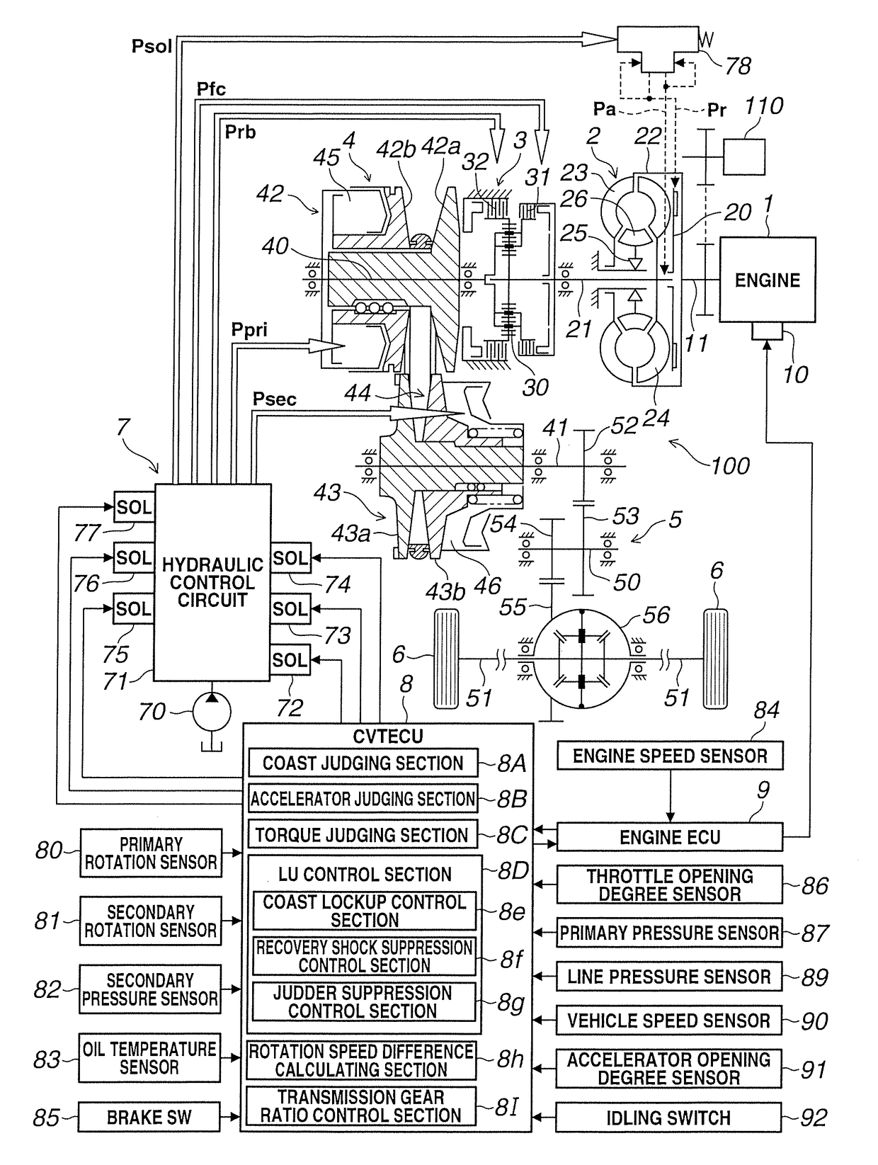
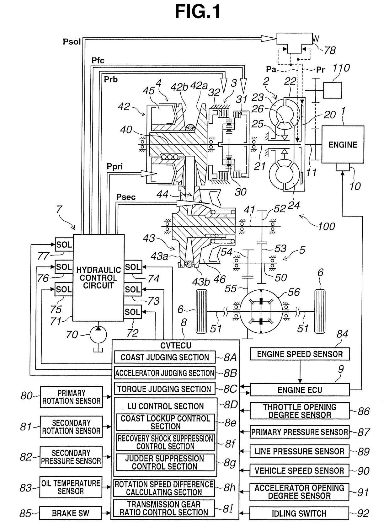
[0029][1.1. Overall System Configuration]

[0030]FIG. 1 is a c...


PUM


Abstract

A control device for an automatic transmission includes: a first engagement control section configured to bring the lockup clutch to a full engagement state after a rotation of the internal combustion engine is increased in a slip engagement state while a torque transmission capacity of the lockup clutch is increased, and a second engagement control section configured to add a predetermined capacity to the increased torque transmission capacity when the torque judging section judges an increase of the output torque of the internal combustion engine in a state where a sensed rotation speed difference in the slip engagement state of the engagement state of the first engagement control is increased to be equal to or greater than a first predetermined value, and then decreased to be equal to or smaller than a second predetermined value smaller than the first predetermined value.

Description

TECHNICAL FIELD[0001]This invention relates to a control of an automatic transmission which is mounted on a vehicle, and includes a torque converter with a lockup clutch.BACKGROUND ART[0002]An automatic clutch of a vehicle such as an automobile often includes a torque converter which is disposed between an engine and an automatic transmission, and which has a lockup clutch. A patent document 1 discloses the control of the lockup clutch configured to prohibit a full engagement (lockup) of the lockup clutch when an accelerator is switched to an ON state at the lockup (that is, a coast lockup) during a coast traveling by an accelerator OFF, for avoiding a large torque shock generated by an operation of a reverse torque in which a torque transmission direction is reversed.[0003]As described above, when the accelerator is switched to the ON state at the coast lockup and the full engagement of the lockup clutch is prohibited, the lockup clutch is brought to a full disengagement state or a...

Claims


Application Information

Patent Timeline
Patent Type & Authority Applications(United States)
IPC IPC(8): F16H61/14B60W30/18
CPCF16H61/14B60W30/18072F16H2061/146B60W2510/0233B60W2510/0657F16H59/18F16H61/143F16H2059/186F16H2059/467F16H59/141F16H59/38
Inventor KAMIYA, KOHEIHONMA, TOMOAKISUZUKI, AKITOENDO, YASUHIRO
Owner JATCO LTD
Why Eureka
Try Eureka