
Structure for preventing vibration of solenoid valve

a solenoid valve and structure technology, applied in the direction of valve operating means/release devices, shock absorbers, electrochemical generators, etc., can solve the problems of deteriorating performance in the control of the flow rate of fuel in the flow path, severe vibration and noise, and adverse noise reduction properties. , to achieve the effect of reducing vibration and noise of the solenoid valve, reducing the friction between the plunger and the yoke, and increasing the frictional for

Inactive Publication Date: 2018-03-15
HYUNDAI MOTOR CO LTD
View PDF10 Cites 3 Cited by
  • Summary
  • Abstract
  • Description
  • Claims
  • Application Information

AI Technical Summary

Benefits of technology

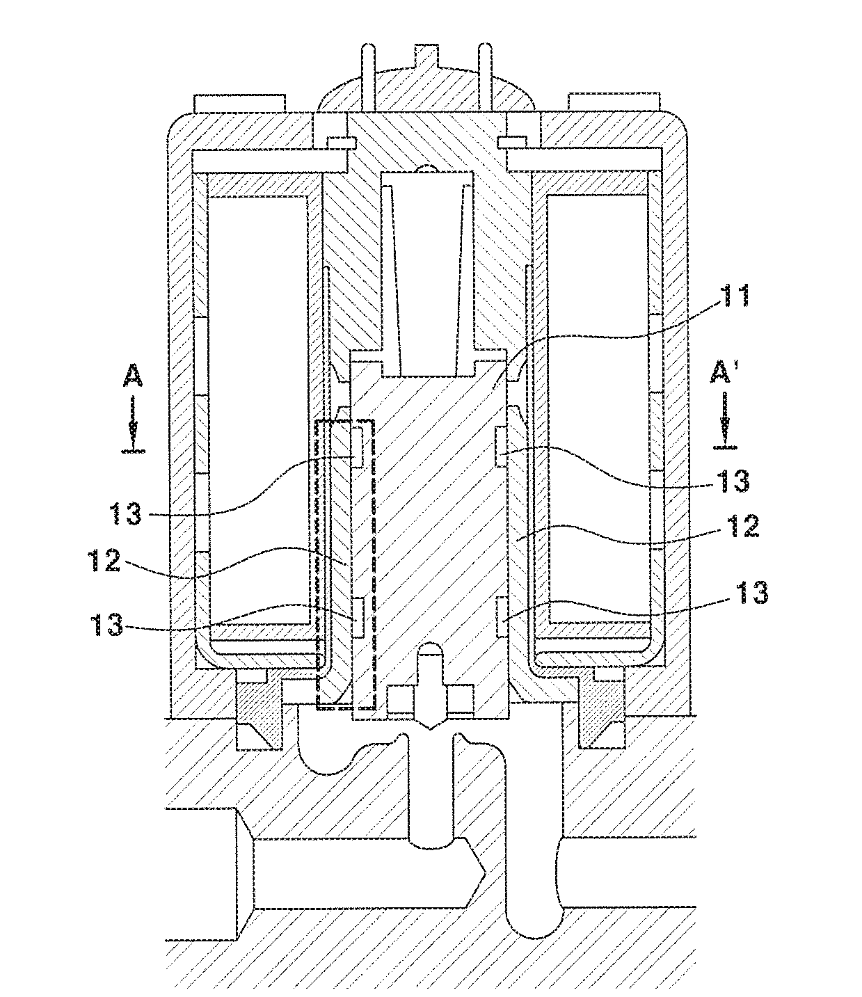
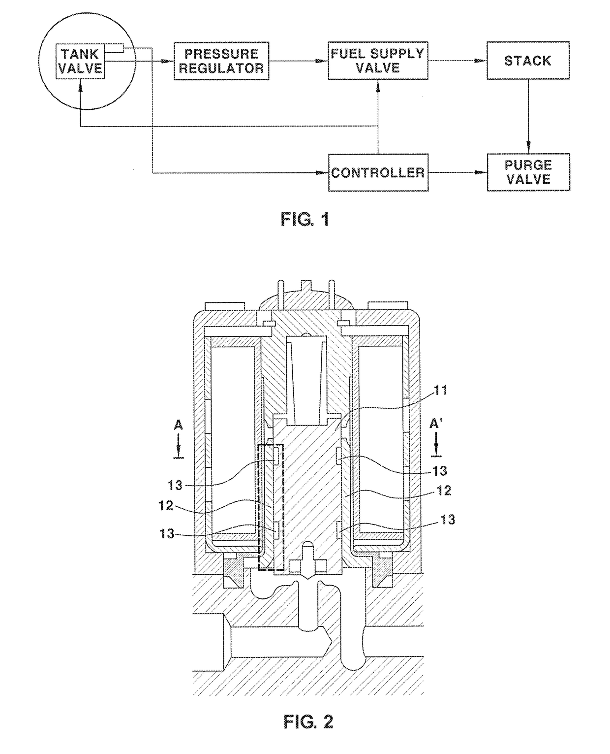
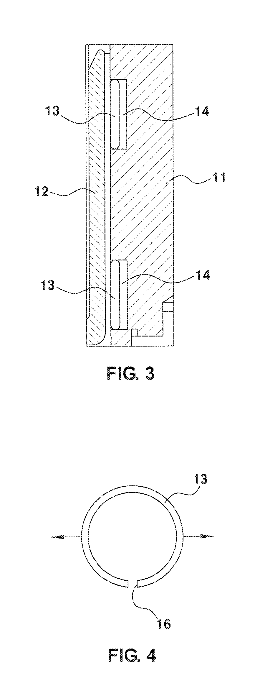
The present invention aims to provide a structure for reducing vibration and noise of a solenoid valve. The friction part is configured by inserting a friction member between drive units of the solenoid valve, namely, between a plunger and a yoke, and one side of the friction member can be attached to either the plunger or the yoke. The friction member comes into close contact with the yoke, thereby increasing frictional force between the plunger and the yoke, which can prevent the stuck phenomenon of the plunger. This structure can also accurately control the movement speed of the plunger and minimize noise and vibration caused by the valve, improving the marketability of the vehicle.

Problems solved by technology

However, when high-pressure fuel having a pressure of about 9 to 20 bar flows into the valve at a high speed, the valve resonates in a vertical direction, which may cause severe vibration and noise.
For this reason, there are problems in that the vibration and the noise have a severe adverse effect on noise reducing properties of a vehicle equipped with the fuel cell system, and performance in respect of controlling a flow rate of fuel in the flow path deteriorates.

Method used


Image

  • Structure for preventing vibration of solenoid valve
  • Structure for preventing vibration of solenoid valve
  • Structure for preventing vibration of solenoid valve

Examples


Embodiment Construction

[0037]Hereinafter reference will now be made in detail to various embodiments of the present disclosure, examples of which are illustrated in the accompanying drawings and described below. While the invention will be described in conjunction with exemplary embodiments, it will be understood that present description is not intended to limit the invention to those exemplary embodiments. On the contrary, the invention is intended to cover not only the exemplary embodiments, but also various alternatives, modifications, equivalents, and other embodiments, which may be included within the spirit and scope of the invention as defined by the appended claims.

[0038]Hereinafter, exemplary embodiments of the present disclosure will be described in more detail with reference to the accompanying drawings. The exemplary embodiments of the present disclosure may be modified in various forms, and the scope of the present disclosure should not be interpreted as being limited to the following exempla...


PUM


Abstract

A structure for preventing vibration of a solenoid valve includes: a plunger which opens and closes a flow path by moving inside the solenoid valve; a yoke attached to an inner surface of a valve core; and a friction member disposed along an outer circumferential surface of the plunger between the plunger and the yoke, in which the friction member presses the yoke between the yoke and the plunger.

Description

CROSS-REFERENCE TO RELATED APPLICATION[0001]This application claims under 35 U.S.C. § 119(a) the benefit of priority to Korean Patent Application No. 10-2016-0117052 filed on Sep. 12, 2016, the entire content of which is incorporated herein by reference.TECHNICAL FIELD[0002]The present disclosure relates to a structure for preventing vibration, which may be generated in a solenoid valve due to behavior of a plunger positioned in the solenoid valve during a process of supplying hydrogen from a fuel tank to a stack through the solenoid valve, and for preventing noise caused by the vibration.BACKGROUND[0003]A fuel cell system reduces pressure of hydrogen supplied from a high-pressure fuel tank and supplies the hydrogen to a stack, and operations of opening and closing a flow path in a hydrogen supply line is generally performed by a solenoid valve.[0004]In general, a solenoid valve is a device for opening or closing the flow path by changing an inlet or an outlet between a valve cylind...

Claims


Application Information

Patent Timeline
IPC IPC(8): F16K31/06F16F7/09F16F13/00F16K47/02
CPCF16K31/0689F16F7/095F16F2222/04F16K47/02F16F2224/02F16F13/005F16K31/0675F16K31/0655H01M8/04201H01M2250/20Y02T90/40Y02E60/50F16K31/0644F16K31/0658F16K1/34H01M8/04089H01F7/18
Inventor JUNG, SE KWONKWON, BU KIL
Owner HYUNDAI MOTOR CO LTD
Learn More