Supercharge Your Innovation With Domain-Expert AI Agents!

Systems and methods for pulse descriptor word generation using blind source separation

a technology of source separation and pulse descriptor, applied in the field of high-performance systems and methods for generating pulse descriptors using blind source separation, can solve the problems of reducing the accuracy of estimation of resultant pdw parameters, fixed bandwidth channels, and values of center frequency, and achieve the effect of convenient updating

Active Publication Date: 2018-03-15
THE BOEING CO +1
View PDF6 Cites 1 Cited by
  • Summary
  • Abstract
  • Description
  • Claims
  • Application Information

AI Technical Summary

Benefits of technology

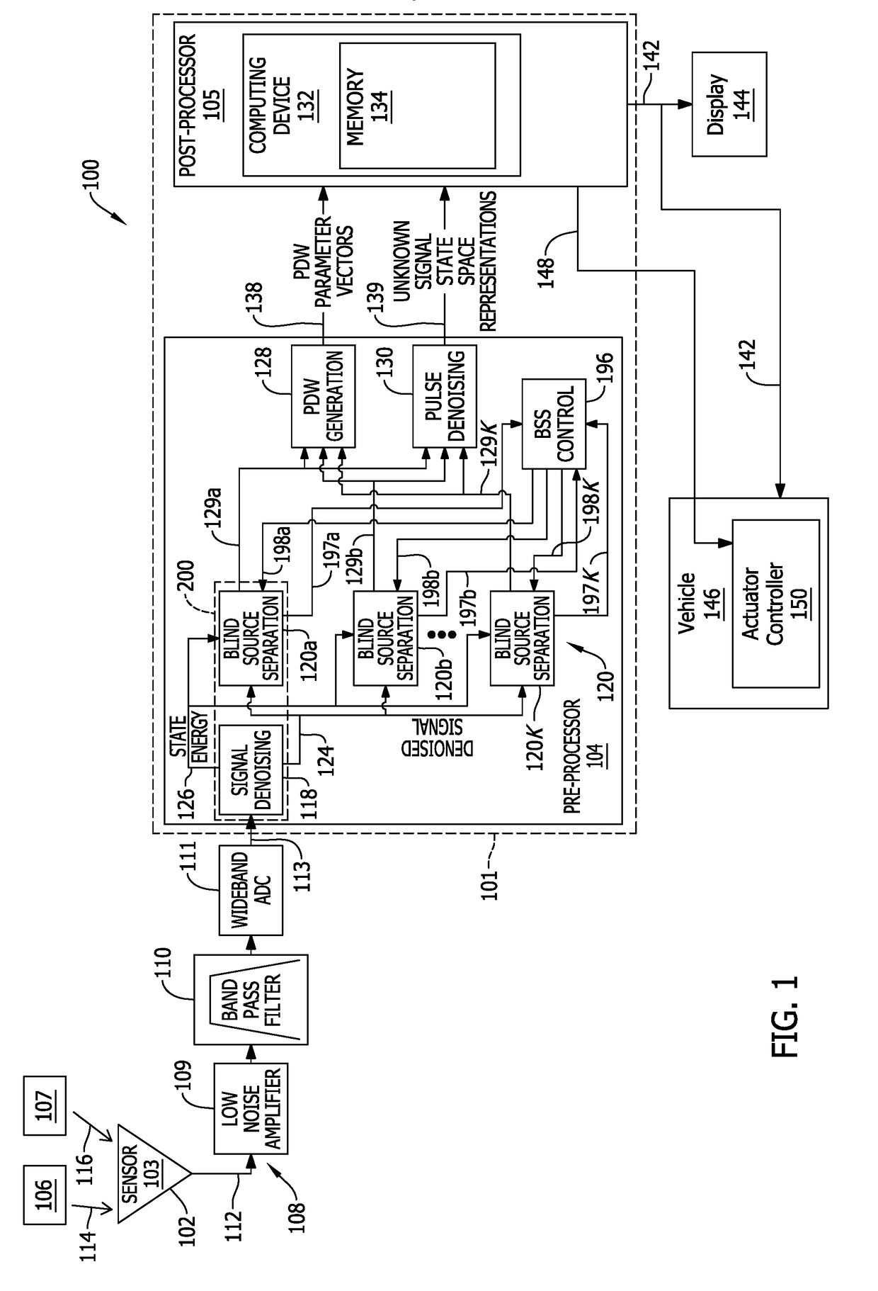
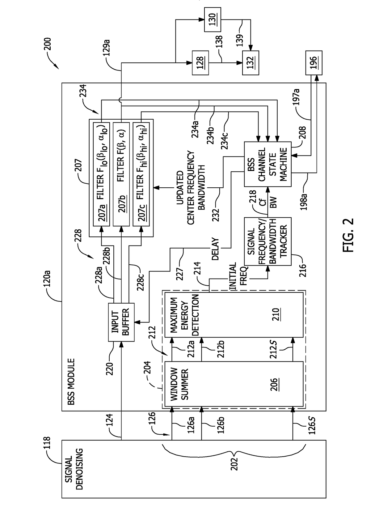
This patent describes a system for processing multiple signals over time to create a single parameterized data (PDW) waveform. The system includes a sensor to collect the signals and a processor to filter the signals and generate the PDW waveform. The processor contains multiple BSS modules, each with a filtering subsystem and a PDW generation module. These modules work simultaneously to filter the signals, generate the PDW waveform, and update the filters with new data. The technical effect of this invention is a more efficient and accurate way to analyze multiple signals and detect relevant patterns over time.

Problems solved by technology

In at least some known PDW vector signal processing systems, fixed bandwidth channels reduce accuracy of estimates of resultant PDW parameters such as estimated values of center frequency, bandwidth, pulse time, and pulse width of signals received from a plurality of target signal emitters (e.g., radar signals).
Further, even when size, weight, and cost are not critical design constraints, at least some known systems and methods for PDW vector signal processing suffer from diminished efficiency and accuracy in continuously generating high quality PDW parameter vectors suitable for improved deinterleaving methods.

Method used


Image

  • Systems and methods for pulse descriptor word generation using blind source separation
  • Systems and methods for pulse descriptor word generation using blind source separation
  • Systems and methods for pulse descriptor word generation using blind source separation

Examples


Embodiment Construction

[0025]In the following specification and the claims, reference will be made to a number of terms, which shall be defined to have the following meanings.

[0026]The singular forms “a”, “an”, and “the” include plural references unless the context clearly dictates otherwise.

[0027]“Optional” or “optionally” means that the subsequently described event or circumstance may or may not occur, and that the description includes instances where the event occurs and instances where it does not.

[0028]Approximating language, as used herein throughout the specification and claims, may be applied to modify any quantitative representation that could permissibly vary without resulting in a change in the basic function to which it is related. Accordingly, a value modified by a term or terms, such as “about”, “approximately”, and “substantially”, are not to be limited to the precise value specified. In at least some instances, the approximating language may correspond to the precision of an instrument for...


PUM


Abstract

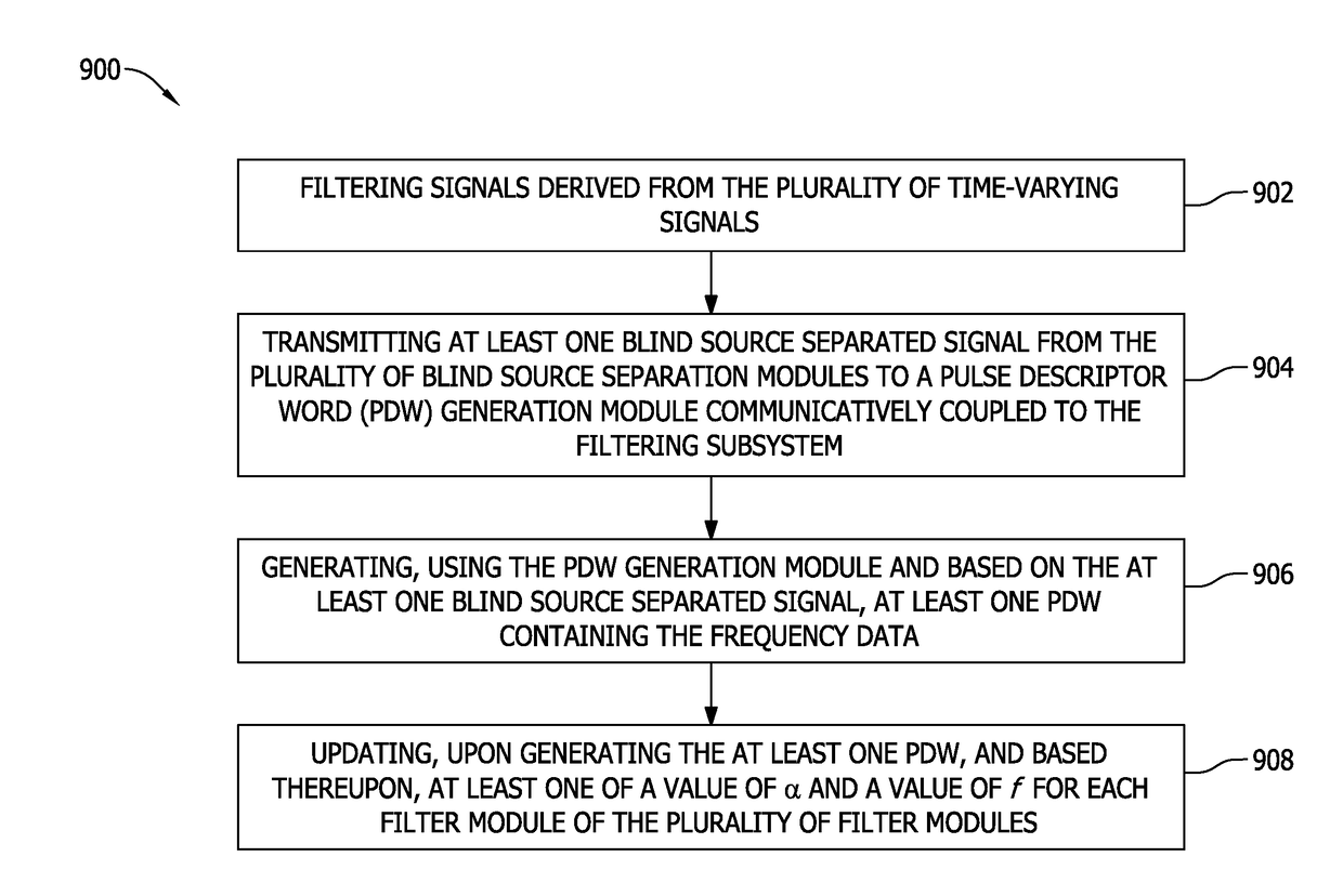
A method for generating pulse descriptor words (PDWs) including frequency and / or bandwidth data from time-varying signals received by a sensor includes filtering, at a plurality of blind source separation (BSS) modules, signals derived from the time-varying signals, each BSS module including a filtering subsystem having a plurality of filter modules. Each filter module has a frequency filter coefficient (α) and is parameterized by a center frequency (f). The method also includes transmitting at least one blind source separated signal from the BSS modules to a PDW generation module communicatively coupled to the filtering subsystem. The method further includes generating, using the PDW generation module and based on the blind source separated signal, at least one PDW parameter vector signal containing the frequency data. The method also includes updating, upon generating and based on the PDW parameter vector signal, values of α and / or f for each filter module.

Description

BACKGROUND[0001]The field of the disclosure relates generally to pulse descriptor word (PDW) vector signal processing, and, more specifically, to high performance systems and methods for PDW generation using blind source separation.[0002]In known PDW vector signal processing systems and methods, fixed bandwidth channels are used to generate PDW vectors for deinterleaving into constituent PDW data blocks (e.g., parameters). In at least some known PDW vector signal processing systems, fixed bandwidth channels reduce accuracy of estimates of resultant PDW parameters such as estimated values of center frequency, bandwidth, pulse time, and pulse width of signals received from a plurality of target signal emitters (e.g., radar signals). In order to improve speed and accuracy for useful estimates of PDW parameter values, such fixed bandwidth channel-based PDW vector signal processing systems require larger and more complex processor architectures. Further, even when size, weight, and cost ...

Claims


Application Information

Patent Timeline
IPC IPC(8): G01S7/292G01S7/00G01S13/66
CPCG01S7/2923G01S13/66G01S7/006G01S7/021G01R23/155G01S7/36
Inventor RAY, GARY ALANPETRE, PETERMARTIN, CHARLES E.RAO, SHANKAR R.
Owner THE BOEING CO
Features
  • R&D
  • Intellectual Property
  • Life Sciences
  • Materials
  • Tech Scout
  • Unparalleled Data Quality
  • Higher Quality Content
  • 60% Fewer Hallucinations
Learn More