Imaging optical lens system, image capturing apparatus and electronic device

an image capturing apparatus and optical lens technology, applied in the field of compact imaging optical lens systems and image capturing apparatuses, can solve the problems of inability to optically adjust the depth of focus, the limitations of imaging optical lens systems and their aperture sizes, and the increased requirements of the photo processing function of these devices by most users

Active Publication Date: 2018-03-15
LARGAN PRECISION
View PDF0 Cites 51 Cited by
  • Summary
  • Abstract
  • Description
  • Claims
  • Application Information

AI Technical Summary

Benefits of technology

[0009]According to another aspect of the present disclosure, an imaging optical lens system includes six lens elements, the six lens elements being, in order from an object side to an image side, a first lens element, a second lens element, a third lens element, a fourth lens element, a fifth lens element and a sixth lens element. The first lens element has positive refractive power. The fifth lens element has an object-side surface being convex in a paraxial region thereof and an image-side surface being concave in a paraxial region thereof, wherein the object-side surface and the image-side surface of the fifth lens element are both aspheric. The sixth lens element has an image-side surface being concave in a paraxial region thereof, wherein an object-side surface and the image-side surface of the sixth lens element are both aspheric, and the image-side surface of the sixth lens element includes at least one convex critical point in an off-axial region thereof. When an axial distance between the second lens element and the third lens element is T23, an axial distance between the fifth lens element and the sixth lens element is T56, a central thickness of the second lens element is CT2, a central thickness of the third lens element is CT3, a central thickness of the sixth lens element is CT6, a curvature radius of an object-side surface of the second lens element is R3, and a curvature radius of an image-side surface of the second lens element is R4, the following conditions are satisfied:
[0010]According to another aspect of the present disclosure, an imaging optical lens system includes six lens elements, the six lens elements being, in order from an object side to an image side, a first lens element, a second lens element, a third lens element, a fourth lens element, a fifth lens element and a sixth lens element. The first lens element has positive refractive power. The third lens element has an image-side surface being concave in a paraxial region thereof, wherein an object-side surface and the image-side surface of the third lens element are both aspheric, and the image-side surface of the third lens element includes at least one convex shape in an off-axial region thereof. The fourth lens element has an object-side surface and an image-side surface being both aspheric. The fifth lens element has an image-side surface being concave in a paraxial region thereof, wherein an object-side surface and the image-side surface of the fifth lens element are both aspheric. The sixth lens element has an image-side surface being concave in a paraxial region thereof, wherein an object-side surface and the image-side surface of the sixth lens element are both aspheric, and the image-side surface of the sixth lens element includes at least one convex critical point in an off-axial region thereof. When an axial distance between the second lens element and the third lens element is T23, an axial distance between the fifth lens element and the sixth lens element is T56, a central thickness of the second lens element is CT2, a central thickness of the third lens element is CT3, and a central thickness of the sixth lens element is CT6, the following conditions are satisfied:
[0011]According to another aspect of the present disclosure, an image capturing apparatus includes an imaging optical lens system having at least six lens elements and includes an aperture adjustment unit. A first lens element is one of the six lens elements closest to an object side of the imaging optical lens system. When an axial distance between an object-side surface of the first lens element and an image surface is TL, a maximum image height of the imaging optical lens system is ImgH, a minimum entrance pupil diameter of the imaging optical lens system is EPDmin, and a maximum entrance pupil diameter of the imaging optical lens system is EPDmax, the following conditions are satisfied:

Problems solved by technology

With the popularity of smart electronic devices and recent technology advances, requirements for photographing functions of these devices from most users are now even more demanding.
However, the volume of these imaging optical lens systems and their aperture sizes are often limited by the compact design of smart electronic devices, and it results in failing to optically adjust depth of focus, digital focusing inaccuracy and etc.
However, conventional imaging optical lens systems applied to smart electronic devices usually have the configurations of short total track lengths, so that the axial distances between lens elements are too small to insert elements like shutters, MEMS (Microelectromechanical Systems), filters, spacers and so on between thereof.
It makes elements such as the shutter to be located in the front end of the imaging optical lens system, the position closest to an imaged object, vulnerable from outside physical abuses.
Therefore, the photographing functions of conventional imaging optical lens systems are limited by the smaller axial distances between lens elements, so there is an urgent need in developing a high quality imaging optical lens system with characteristics of both compact size and greater axial distances between lens elements.

Method used


Image

  • Imaging optical lens system, image capturing apparatus and electronic device
  • Imaging optical lens system, image capturing apparatus and electronic device
  • Imaging optical lens system, image capturing apparatus and electronic device

Examples


1st embodiment

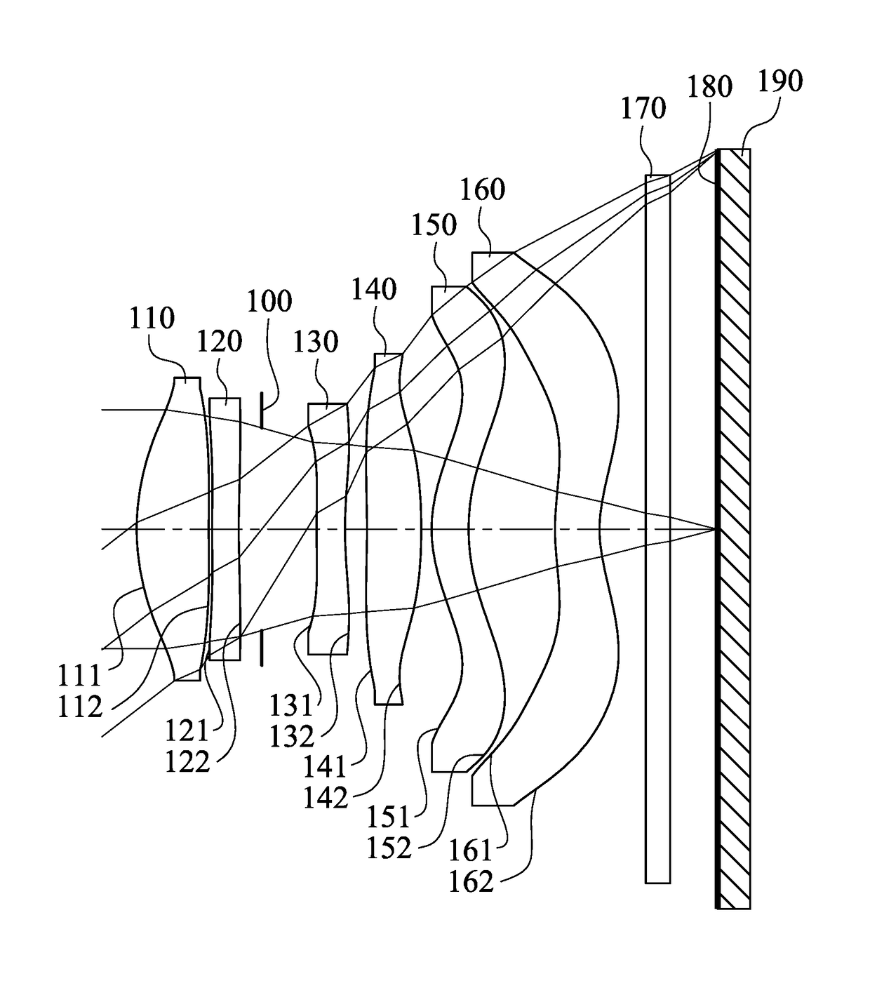
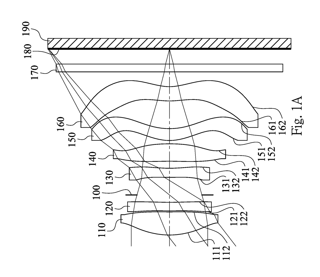
[0086]FIG. 1A is a schematic view of an image capturing apparatus according to the 1st embodiment of the present disclosure. FIG. 2A shows, in order from left to right, spherical aberration curves, astigmatic field curves and a distortion curve of the image capturing apparatus according to FIG. 1A. In FIG. 1A, the image capturing apparatus includes the imaging optical lens system (its reference numeral is omitted) and an image sensor 190. The imaging optical lens system includes, in order from an object side to an image side, a first lens element 110, a second lens element 120, an aperture stop 100, a third lens element 130, a fourth lens element 140, a fifth lens element 150, a sixth lens element 160, an IR-cut filter 170 and an image surface 180. The image sensor 190 is disposed on the image surface 180 of the imaging optical lens system. There is an air gap and no relative movement between every two of the first lens element 110, the second lens element 120, the third lens elemen...

2nd embodiment

[0117]FIG. 3 is a schematic view of an image capturing apparatus according to the 2nd embodiment of the present disclosure. FIG. 4 shows, in order from left to right, spherical aberration curves, astigmatic field curves and a distortion curve of the image capturing apparatus according to the 2nd embodiment. In FIG. 3, the image capturing apparatus includes the imaging optical lens system (its reference numeral is omitted) and an image sensor 290. The imaging optical lens system includes, in order from an object side to an image side, a first lens element 210, a second lens element 220, an aperture stop 200, a third lens element 230, a fourth lens element 240, a fifth lens element 250, a sixth lens element 260, an IR-cut filter 270 and an image surface 280. The image sensor 290 is disposed on the image surface 280 of the imaging optical lens system. There is an air gap and no relative movement between every two of the first lens element 210, the second lens element 220, the third len...

3rd embodiment

[0129]FIG. 5A is a schematic view of an image capturing apparatus according to the 3rd embodiment of the present disclosure. FIG. 6A shows, in order from left to right, spherical aberration curves, astigmatic field curves and a distortion curve of the image capturing apparatus according to FIG. 5A. In FIG. 5A, the image capturing apparatus includes the imaging optical lens system (its reference numeral is omitted) and an image sensor 390. The imaging optical lens system includes, in order from an object side to an image side, a first lens element 310, a second lens element 320, an aperture stop 300, a third lens element 330, a fourth lens element 340, a fifth lens element 350, a sixth lens element 360, an IR-cut filter 370 and an image surface 380. The image sensor 390 is disposed on the image surface 380 of the imaging optical lens system. There is an air gap and no relative movement between every two of the first lens element 310, the second lens element 320, the third lens elemen...


PUM


Abstract

An imaging optical lens system includes six lens elements, the six lens elements being, in order from an object side to an image side, a first lens element, a second lens element, a third lens element, a fourth lens element, a fifth lens element and a sixth lens element. The first lens element has positive refractive power. The third lens element has an image-side surface being concave in a paraxial region thereof. The fifth lens element has an object-side surface and an image-side surface being both aspheric. The sixth lens element has an image-side surface being concave in a paraxial region thereof, wherein an object-side surface and the image-side surface of the sixth lens element are both aspheric, and the image-side surface of the sixth lens element includes at least one convex critical point in an off-axial region thereof.

Description

RELATED APPLICATIONS[0001]This application claims priority to Taiwan Application Serial Number 105129623, filed Sep. 12, 2016, which is herein incorporated by reference.BACKGROUNDTechnical Field[0002]The present disclosure relates to an imaging optical lens system and an image capturing apparatus. More particularly, the present disclosure relates to a compact imaging optical lens system and an image capturing apparatus which are applicable to electronic devices.Description of Related Art[0003]With the popularity of smart electronic devices and recent technology advances, requirements for photographing functions of these devices from most users are now even more demanding. In order to take pictures with a depth of field effect or lower noise level at night, smart electronic devices should be equipped with high resolution imaging optical lens systems with large apertures. However, the volume of these imaging optical lens systems and their aperture sizes are often limited by the compac...

Claims


Application Information

Patent Timeline
Patent Type & Authority Applications(United States)
IPC IPC(8): G02B13/00G02B9/62G02B5/20
CPCG02B13/0045G02B5/208G02B9/62
Inventor LIN, CHENG-CHENCHEN, CHUN-YENCHEN, WEI-YU
Owner LARGAN PRECISION
Why Eureka
Try Eureka