Keyswitch with adjustable tactile feedback

a technology of adjustable tactile feedback and keyswitch, which is applied in the field of keyswitch, can solve the problems of high replacement cost, limited flexibility in use and operation convenience of mechanical keyswitch, and high replacement cos

Active Publication Date: 2018-03-15
DARFON ELECTRONICS CORP
View PDF0 Cites 17 Cited by
  • Summary
  • Abstract
  • Description
  • Claims
  • Application Information

AI Technical Summary

Benefits of technology

[0004]The present invention provides a keyswitch. The keyswitch includes a cap, a base, a resilient arm, an internal sleeve, an external sleeve, and an elastic member. The base has a pillar extending along a Z-axis. The Z-axis, an X-axis and a Y-axis are perpendicular to each other. The resilient arm is adjacent to the pillar. The internal sleeve jackets the pillar and has a first outer annular surface. A top end of the internal sleeve abuts against the cap. A transverse slot is formed on the first outer annular surface and extends substantially along a plane containing the X-axis and the Y-axis. The elastic member is disposed between the internal sleeve and the base for driving the internal sleeve to move away from the base. The external sleeve has a second outer annular surface and an inner annular surface and jackets the internal sleeve via the inner annular surface. The second outer annular surface has a convex portion, a concave portion, and a first arc-shaped bar. The convex portion, the concave portion, and the first arc-shaped bar extend substantially along the plane containing the X-axis and the Y-axis. A protruding block is formed on the inner annular surface and is movably inserted in...

Problems solved by technology

That is to say, a conventional mechanical keyswitch can only provide one single kind of tactile feedback without a tactile feedback adjusting funct...

Method used


Image

  • Keyswitch with adjustable tactile feedback
  • Keyswitch with adjustable tactile feedback
  • Keyswitch with adjustable tactile feedback

Examples


first embodiment

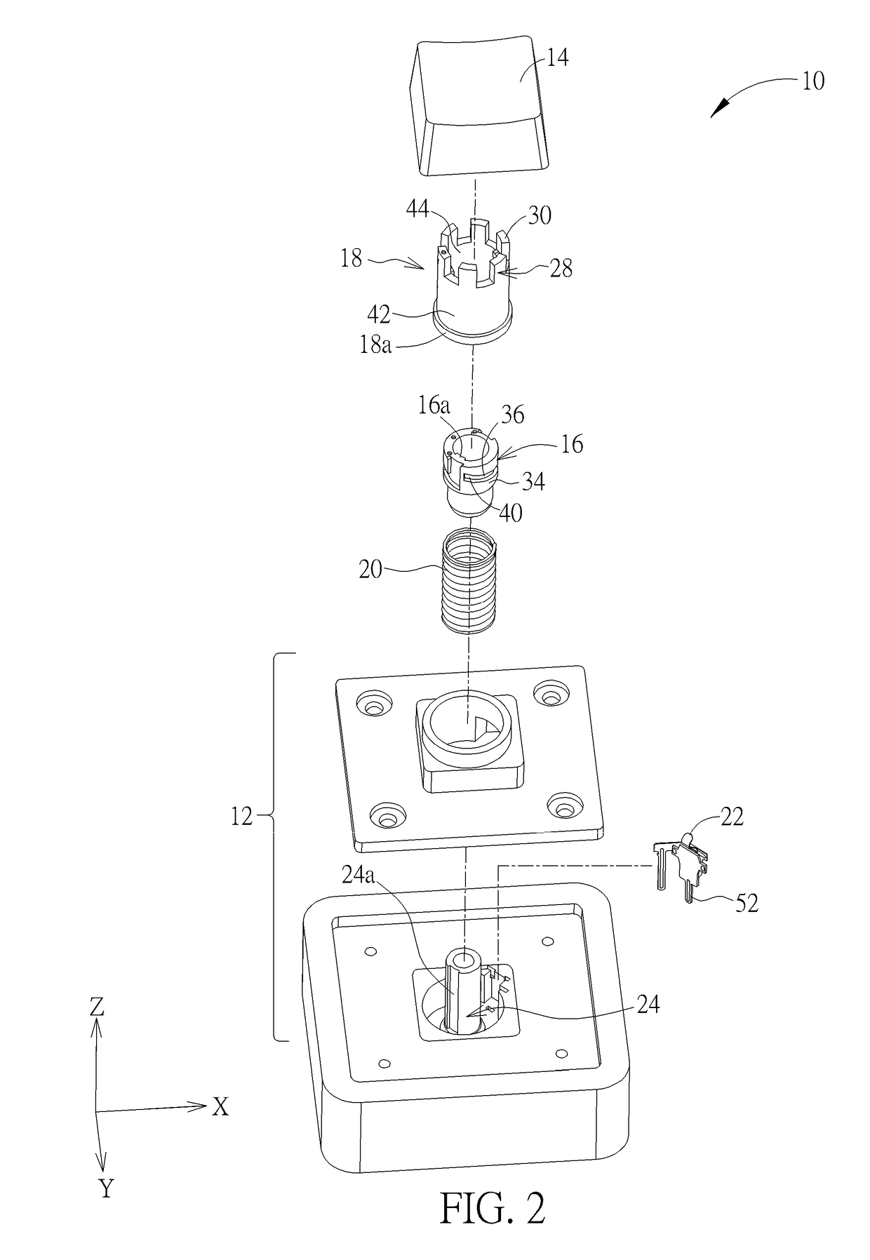
[0074]The keyswitch 100 includes the base 12, the cap 14, the internal sleeve 102, the external sleeve 104, the elastic member 20, and the resilient arm 22 adjacent to the pillar 24 (disposal of the contact point 52 could be selectively applied to this embodiment). After the external sleeve 104 is assembled with the internal sleeve 102 via engagement of the upper engaging structure 28 and the cap engaging structure 26, the internal sleeve 102 and the external sleeve 104 can move relatively along the Z-axis or rotate relatively around the Z-axis, but relative movement between the internal sleeve 102 and the external sleeve 104 along the plane containing the X-axis and the Y-axis is constrained. The internal sleeve 102 can have a first outer annular surface 103 and a transverse slot 106 is formed on the first outer annular surface 103. If there is no need to perform the preload adjustment operation as mentioned in the first embodiment, the transverse slot 106 can extend along the plan...

third embodiment

[0088]For example, please refer to FIG. 22, FIG. 23, FIG. 23A, FIG. 23B, FIG. 24, FIG. 25, FIG. 26, FIG. 27, FIG. 28, FIG. 28, FIG. 30, and FIG. 31. FIG. 22 is a diagram of a keyswitch 200 according to the present invention. FIG. 23 is an exploded diagram of the external sleeve 206 and a base 202 in FIG. 22. FIG. 23A is an enlarged diagram of the external sleeve 206 in FIG. 22. FIG. 23B is an enlarged diagram of the base 202 in FIG. 23B. FIG. 24 is a cross-sectional diagram of the keyswitch 200 in FIG. 22 along a cross-sectional line F-F′ when the cap 14 is assembled with the base 202. FIG. 25 is a cross-sectional diagram of the cap 14 in FIG. 24 being pressed. FIG. 26 is a partial exploded diagram of the keyswitch 200 in FIG. 22 when the external sleeve 206 continues rotating (clockwise from a top view) to make a protruding point 218 of the external sleeve 206 being located above a first bock 210. FIG. 27 is a cross-sectional diagram of the keyswitch 200 in FIG. 26 along a cross-se...


PUM


Abstract

A keyswitch includes a cap, internal and external sleeves, a resilient arm, a base having a pillar, and an elastic member abutting against the internal sleeve and the base. The internal sleeve jackets the pillar, abuts against the cap and has a first outer annular surface with a transverse slot. The external sleeve jackets the internal sleeve and has a protruding block movably inserted into the transverse slot for guiding the external sleeve to rotate and a second outer annular surface having concave and convex portions and an arc-shaped bar. When the resilient arm abuts against a second position on the convex portion and the cap presses the external sleeve, the resilient arm crosses the arc-shaped bar. When the resilient arm abuts against a first position on the convex portion and the cap presses the external sleeve, the resilient arm does not need to cross the arc-shaped bar.

Description

BACKGROUND OF THE INVENTION1. Field of the Invention[0001]The present invention relates to a keyswitch, and more specifically, to a keyswitch with an adjustable tactile feedback via rotation of an external sleeve relative to a base.2. Description of the Prior Art[0002]A keyboard, which is the most common input device, can be found in variety of electronic apparatuses for users to input characters, symbols, numerals and so on. Furthermore, consumer electronic products to industrial machine tools are all equipped with a keyboard for performing input operations.[0003]In practical application, there are various kinds of keyswitches for providing different tactile feedbacks. For example, a gaming keyboard would indicate that it has red, brown or black keyswitches installed thereon on its packing box to remind the user of what kind of tactile feedback (e.g. high or low triggering position, long or short travel distance, required actuation force, tactile or linear feedback, clicky or non-c...

Claims


Application Information

Patent Timeline
IPC IPC(8): G06F3/01H03K17/96G06F3/02
CPCG06F3/016G06F3/0202H03K17/9643H01H13/85H01H2215/028H01H2227/034H01H2231/008H01H2233/002
Inventor LIU, CHIA-HUNG
Owner DARFON ELECTRONICS CORP
Why Eureka
Try Eureka