Spindle drive apparatus

Active Publication Date: 2018-03-22
STABILUS
View PDF7 Cites 7 Cited by
  • Summary
  • Abstract
  • Description
  • Claims
  • Application Information

AI Technical Summary

Benefits of technology

[0018]In another variant, which makes it easier to assemble the components of the drive

Problems solved by technology

The spindle drive apparatuses that are generally known on the market are disadvantageous in that they are expensive to produce owing to the high number of components of which

Method used


Image

  • Spindle drive apparatus
  • Spindle drive apparatus
  • Spindle drive apparatus

Examples


Embodiment Construction

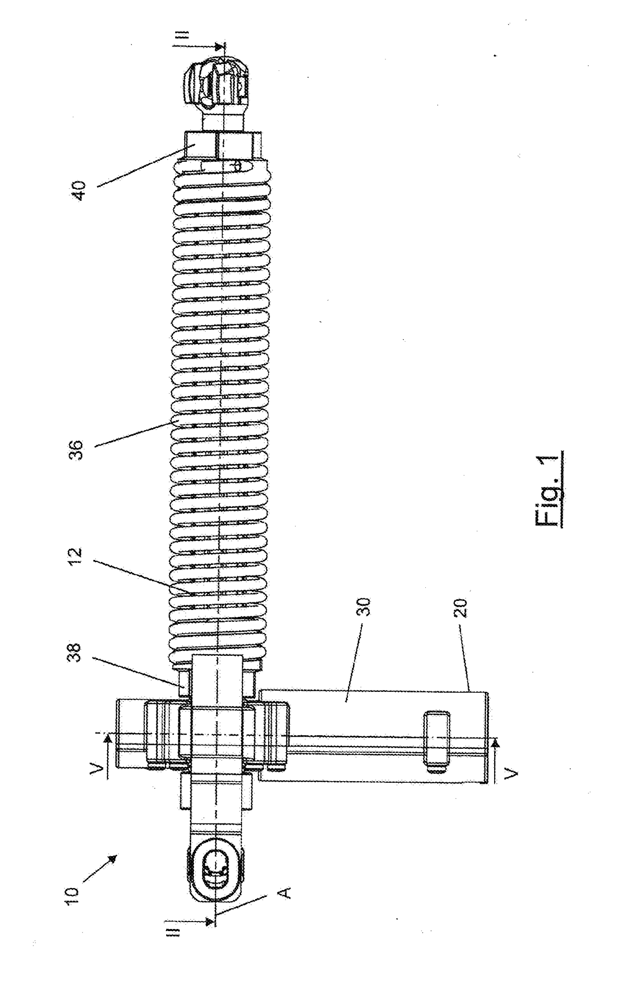
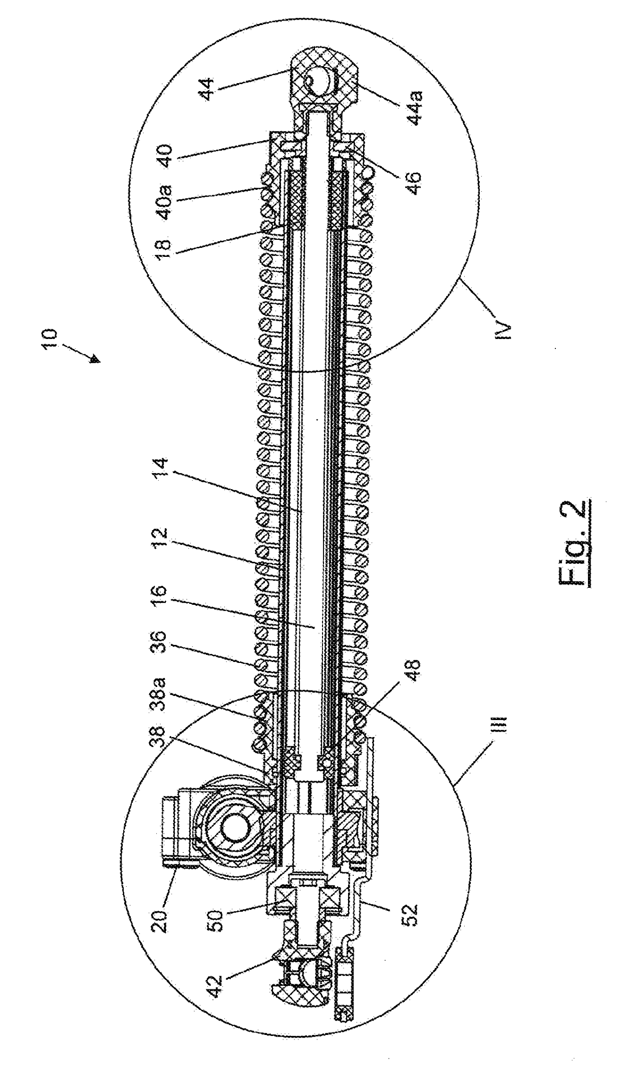
[0027]The spindle drive apparatus 10 comprises a guide tube 12 having a longitudinal axis A, which, in this embodiment, coincides with a central axis of the guide tube 12. A spindle 16 (see also FIGS. 3 and 4) provided with an external thread 14 is housed at least in part in the guide tube 12, which spindle protrudes out of the guide tube 12 at one end thereof. Furthermore, the spindle drive apparatus 10 comprises a spindle nut 18 that is fastened to the guide tube 12 and is in threaded engagement with the external thread 14 of the spindle 16, and a drive assembly 20 comprising a drive unit 22, which is designed as an electric motor 22 in this case (see FIG. 5).

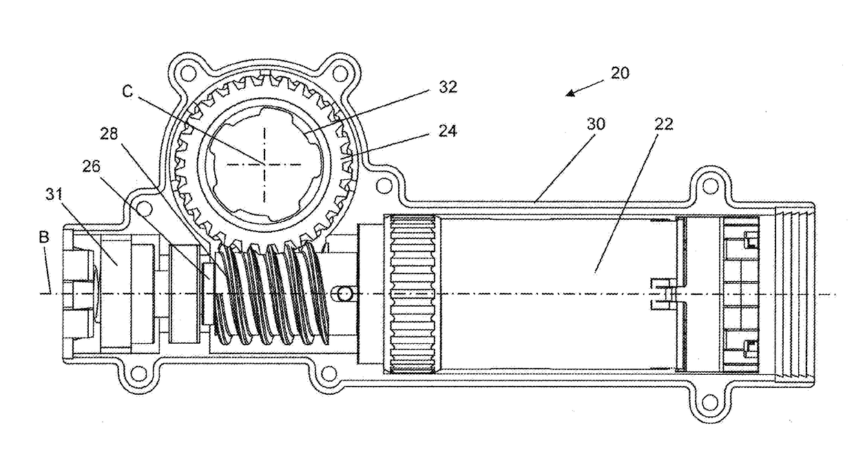
[0028]With reference to FIG. 5, a drive element 24 that is driven by the electric motor 22 surrounds the guide tube 12 and can be rotationally fixed thereto, it being possible to move the drive element 24 and thus the drive assembly 20 along the guide tube 12.

[0029]The electric motor 22 comprises an output shaft 26 on which a...


PUM


Abstract

A spindle drive apparatus includes a guide tube having a connection unit for connecting the spindle drive apparatus to a superordinate assembly, the connection unit fastened to the guide tube for rotation relative thereto, an externally threaded spindle housed at least in part in the guide tube, a further connection unit rotationally fixed to the end of the spindle for connecting the spindle drive apparatus to a further superordinate assembly, a spindle nut is fastened to the guide tube in threaded engagement with the spindle, and a drive assembly has a drive unit, wherein a drive element that is driven by the drive unit surrounds the guide tube and is rotationally fixable thereto, and wherein the drive unit is supported on one of the superordinate assemblies or on an element connected thereto.

Description

BACKGROUND[0001]The invention relates to a spindle drive apparatus, as is used for example to open and close doors and / or tailgates of motor vehicles.[0002]The spindle drive apparatuses that are generally known on the market are disadvantageous in that they are expensive to produce owing to the high number of components of which they are composed. Furthermore, owing to the design of these spindle drive apparatuses, a large amount of installation space has to be available in order for them to be used.BRIEF DESCRIPTION[0003]The object of the present invention is therefore to remedy these drawbacks.[0004]This object is achieved according to the invention by a spindle drive apparatus comprising a guide tube having a longitudinal axis, wherein the guide tube is provided, on one end thereof, with a connection unit for connecting the spindle drive apparatus to a superordinate assembly, i.e. an assembly that is not part of the spindle drive apparatus, and wherein the connection unit is fast...

Claims


Application Information

Patent Timeline
IPC IPC(8): F16H19/00F16H25/04
CPCF16H19/001F16H25/04E05F15/622F16H25/24F16H2025/2084F16H2025/2081F16H2025/209E05F1/1058F16H25/20F16H2025/204E05Y2900/531E05Y2900/546F16H2025/2037
Inventor OSTER, PETER
Owner STABILUS
Why Eureka
Try Eureka