Illumination system comprising heterogeneous fiber arrangement

a fiber arrangement and heterogeneous technology, applied in the field of inspection system, can solve the problems of affecting so as to achieve good imaging, and improve the quality of images

Active Publication Date: 2018-03-22
SCHOTT AG
View PDF28 Cites 6 Cited by
  • Summary
  • Abstract
  • Description
  • Claims
  • Application Information

AI Technical Summary

Benefits of technology

[0012]Therefore, it is a purpose of the invention to provide an illumination system, in particular a fiber arrangement, which can be used to realize a less complex and cost-effective camera- or sensor-based inspection solution.
[0013]The purpose of the invention is achieved by virtue of the fact that the fiber arrangement is designed as a rigid fiber rod, and that a region C is provided between the region A and the region B, said region C suppressing stray light transfers between the regions A and B of the fiber rod. An optical coupling element can be provided at the proximal end of the fiber rod, by means of which optical coupling element, in the operating state, light from the light source can be coupled into the fiber rod and an image at the proximal end of the fiber rod from the region B can be coupled into a camera or into a sensor. Region C allows improvement of the image quality in a surprisingly simple way. In particular, the usually very intensive light for illumination from the image guiding channel through the region B can be shielded from the camera and / or the sensor.
[0014]With such a heterogeneous fiber rod, it is possible, on the one hand to illuminate objects to be inspected and, on the other hand, to evaluate the image reflected back for monitoring a surface with regard to modifications or conspicuous features or position monitoring. This fiber rod additionally allows the camera to be able to be arranged at a distance from the object to be inspected, which is advantageous particularly in the case of expected ambient conditions with regard to moisture and temperature. For medical-applications, this allows the fiber arrangement to be able to be subjected to cleaning and autoclaving processes for reconditioning. By means of this heterogeneous fiber arrangement with a region with a fiber diameter usually used for light guiding (region A) and at least one region with significantly reduced individual fiber diameter (region B) for image guiding, it is possible moreover to reduce the production effort in comparison with an approach with a reduced individual fiber diameter over the entire diameter of the fiber rod. With such fiber rods it is possible to produce in particular so-called dental curing rods (or dental rods for short) which, after treatment of the patient, can easily be demounted from the curing device and be reconditioned or sterilized. In applications in the industrial sector, it is thus possible to realize less complex bushings, e.g. in machine interiors, motors, engines or heating systems, with less assembly efforts. It is as well possible to inspect the quality of connections in connection technology. For analytical purposes and / or water monitoring, it is as well possible to quantify and, if appropriate, characterize the presence of bodies in the liquid.

Problems solved by technology

Such endoscopes generally are therefore very cost-intensive and complex to produce, particularly if high-resolution images of the surface are intended to be transmitted.
Such light undergoing crosstalk can lead to significant deteriorations in image quality and render examinations impossible.
This is a fundamental disadvantage of the fiber rod due to the simplified production method.

Method used


Image

  • Illumination system comprising heterogeneous fiber arrangement
  • Illumination system comprising heterogeneous fiber arrangement
  • Illumination system comprising heterogeneous fiber arrangement

Examples


Embodiment Construction

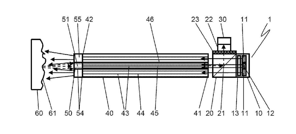
[0045]FIG. 1 schematically shows the construction of an illumination system 1 according to the invention. A rigid fiber arrangement in the form of a fiber rod 40 is illustrated here by way of example.

[0046]In the example shown, the illumination system 1 comprises a light source 10, which as an LED light source is equipped with predominantly an LED type A 11, which emits light in a specific spectral range. In addition, a second LED type B 12 can optionally also be arranged in the light source 10, said second LED type B emitting light in a second spectral range.

[0047]For a curing device for dental fillings, by way of example, the LEDs of the LED type A 11 are designed as LEDs exhibiting blue light emission. The wavelength of the blue light is usually between 390 nm and 520 nm and in this case is coordinated in particular with the reaction kinetics of the dental filling material. The wavelength of the LEDs of the LED type B 12 can be for example in the green or red visible spectral ran...


PUM


Abstract

An illumination system is provided that includes a spatial fiber arrangement with an optical element at the distal end of the fiber arrangement. The fiber arrangement has a first region including individual fibers with a significantly smaller active diameter in comparison with the individual fibers of a remaining region. The optical element at the distal end is assigned the remaining region. The fiber arrangement can be a rigid fiber rod that includes an intermediate region provided between the first region and the remaining region. The intermediate region suppresses stray light transfers between the first and remaining regions. The fiber arrangement can include an optical coupling element at a proximal end of the fiber rod.

Description

CROSS REFERENCE TO RELATED APPLICATIONS[0001]This application claims benefit under 35 U.S.C. § 119(a) of German Patent Application No. 10 2016 216 443 filed Aug. 31, 2016, the entire contents of which are incorporated herein by reference.BACKGROUND OF THE INVENTION1. Field of the Invention[0002]The invention relates to an illumination system for an inspection system, which comprises a spatial fiber arrangement with an optical element at the distal end of the fiber arrangement, and wherein the fiber arrangement has in its cross section at least one region B having individual fibers with a significantly smaller active diameter in comparison with the individual fibers of a remaining region A of the fiber arrangement, and wherein the optical element at the distal end corresponds in particular to said region B. The illumination system is connected to a light source and / or is at least connectable to such a light source and / or assignable thereto. The invention as well comprises the combina...

Claims


Application Information

Patent Timeline
Patent Type & Authority Applications(United States)
IPC IPC(8): G02B23/24G02B6/06
CPCG02B23/2469G02B6/06G02B23/2453G02B23/2446G02B23/2423A61B1/00165A61B1/00167A61B1/0017G02B6/0006G02B6/0008G02B23/26
Inventor SCHULTHEIS, BERNDRUSSERT, HUBERTUSWERNER, HOLGERTABOR, KEVIN
Owner SCHOTT AG
Why Eureka
Try Eureka