ND filter, method for manufacturing said filter, and multi-display device and image forming device using said filter

a technology of filter and filter body, which is applied in the field of nd filter, method for manufacturing said filter, multi-display device and image forming device using said filter, etc., can solve the problems of inability to manufacture physical models for the preparation of original plates, inability to handle shapes, and extreme manufacturing difficulties

Inactive Publication Date: 2003-08-28
OLYMPUS CORP
View PDF6 Cites 7 Cited by
  • Summary
  • Abstract
  • Description
  • Claims
  • Application Information

AI Technical Summary

Problems solved by technology

In such ND filter manufacturing methods, manufacture is easy in cases where the whole surface of a substrate is set at the same transmittance; however, manufacture is extremely difficult in case where it is necessary to vary the transmittance.
However, in the case of the abovementioned conventional ND filter manufacturing method, it is necessary to prepare an original plate that has an optical density distribution in order to obtain a transmittance distribution in the ND filter, so that it is impossible to handle shapes which are such that a physical model for the preparation of the original plate cannot be manufactured.
Accordingly, the preparation of the original plate...

Method used


Image

  • ND filter, method for manufacturing said filter, and multi-display device and image forming device using said filter
  • ND filter, method for manufacturing said filter, and multi-display device and image forming device using said filter
  • ND filter, method for manufacturing said filter, and multi-display device and image forming device using said filter

Examples


first embodiment

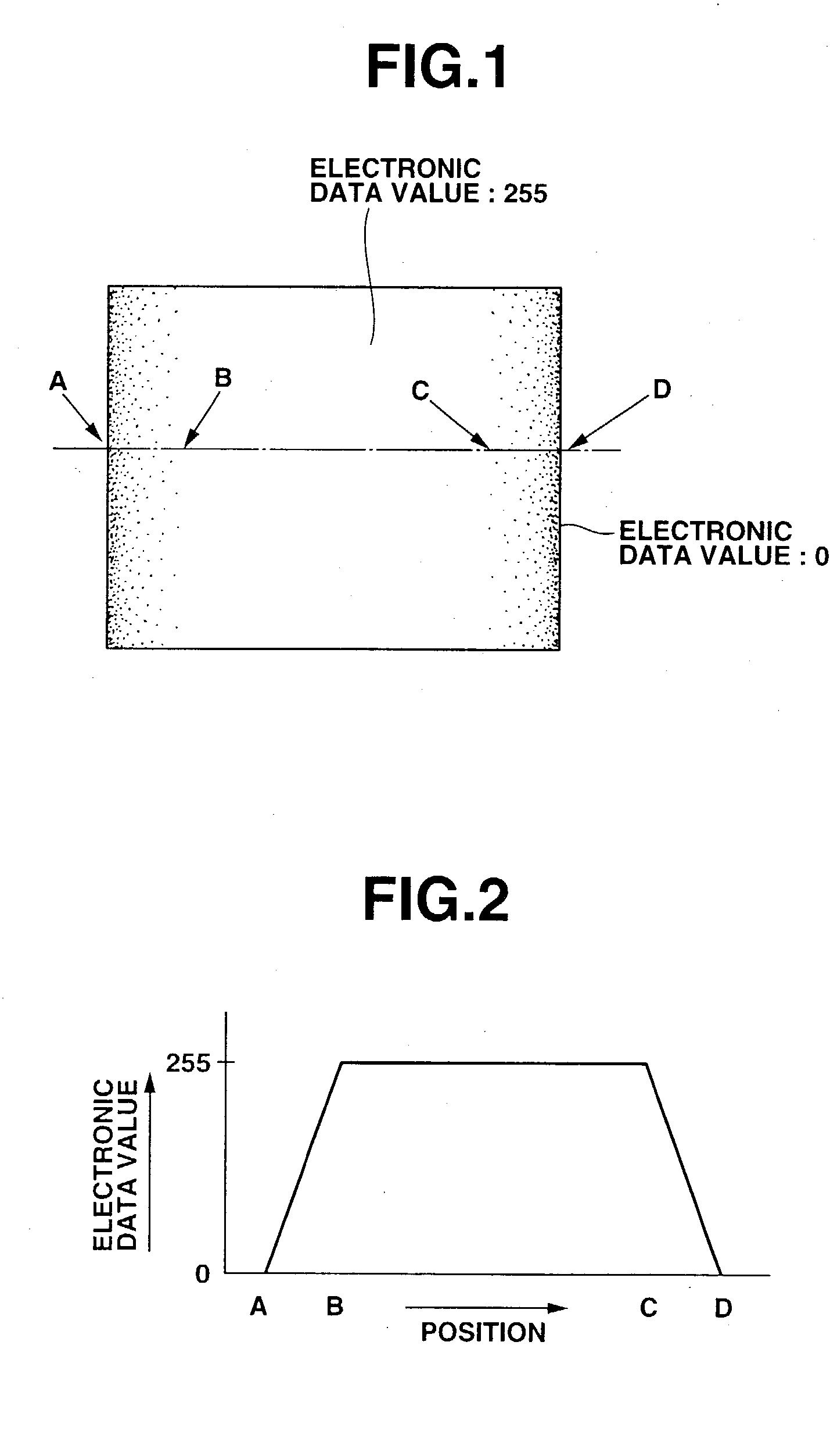
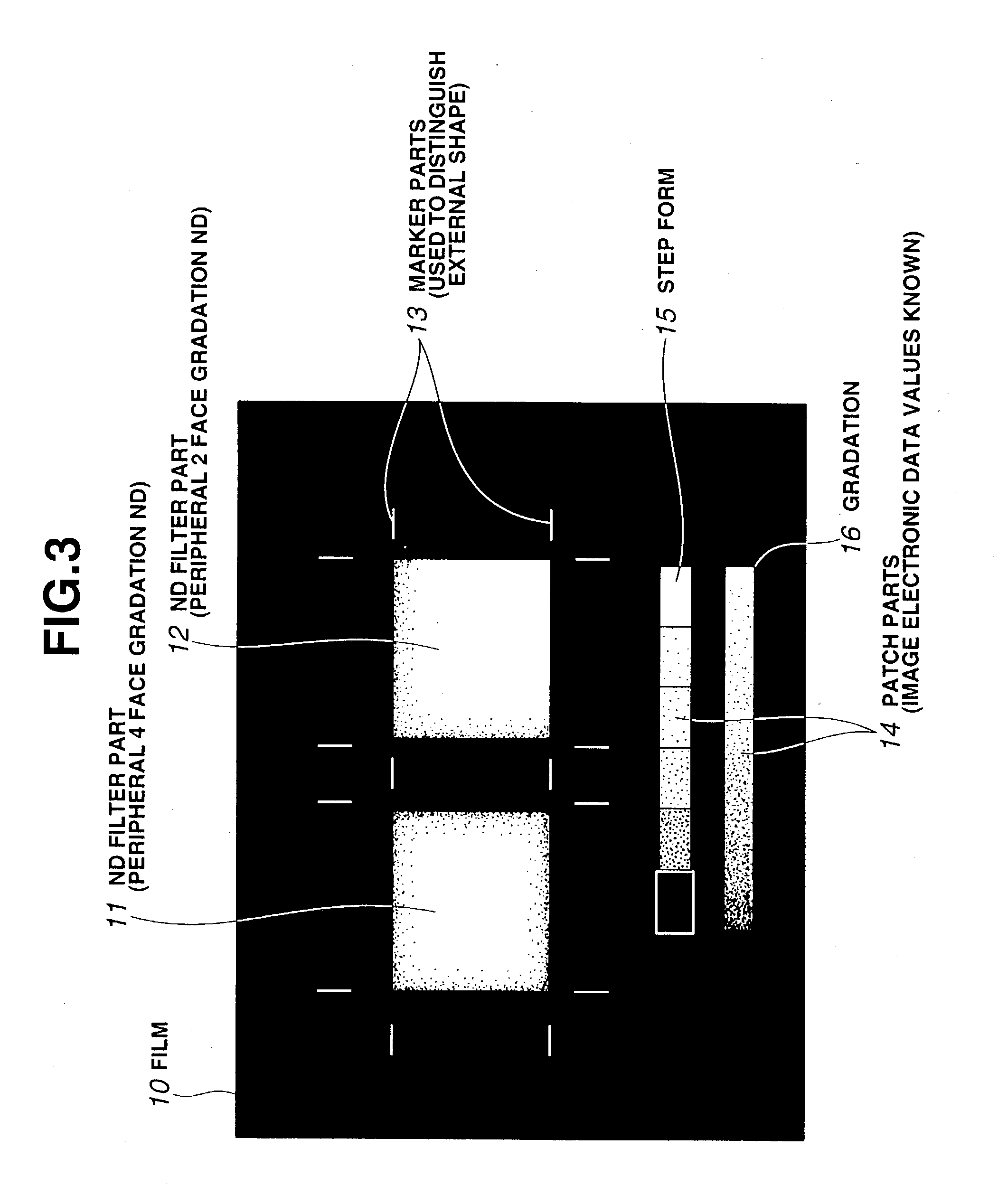
[0048] FIGS. 1 through 7B illustrate the present invention, FIG. 1 is a diagram showing an example of the manufacture of ND filter constituent part by means of image electronic data which has light transmittance information for respective positions used to construct an ND filter, FIG. 2 is a graph which shows the numerical values constituting image electronic data on a line passing through A, B, C and D in FIG. 1, FIG. 3 is a diagram showing an example of manufacture in which a plurality of ND filter constituent parts based on image electronic data prepared in FIG. 1 are formed on a film, FIG. 4 is a flow chart which shows the processes from the preparation of the image electronic data to the completion of the filter manufacturing, FIG. 5 is a graph which shows the target light transmittance on the film, and FIGS. 6A, 6B, 7A and 7B are graphs which illustrate the electronic data correction method used to obtain the target light transmittance.

[0049] This ND filter manufacturing metho...

second embodiment

[0079] FIGS. 8 through 11 illustrate the present invention. FIG. 8 is an enlarged sectional view which shows the film, FIG. 9 is an enlarged sectional view which shows the film in a state in which a colorless transparent sheet has been bonded to the film, FIG. 10 is an enlarged sectional view which shows the film in a state in which the film has been bonded to a polarizing plate on a liquid crystal panel (hereafter referred to as an "LCD"), and FIG. 11 is an enlarged sectional view which shows the film in a state in which anti-reflection-treated (hereafter "AR-treated") colorless transparent sheets have been bonded to the film.

[0080] In the ND filter of this second embodiment, fine irregularity 21a with a size of 1 .mu.m or less is present on the emulsion-coated surface of the film 21 that constitutes the photosensitive material (as show in FIG. 8). Since this surface irregularity 21a causes the diffusion of light in transparent portions as well, such irregularity leads to the gener...

third embodiment

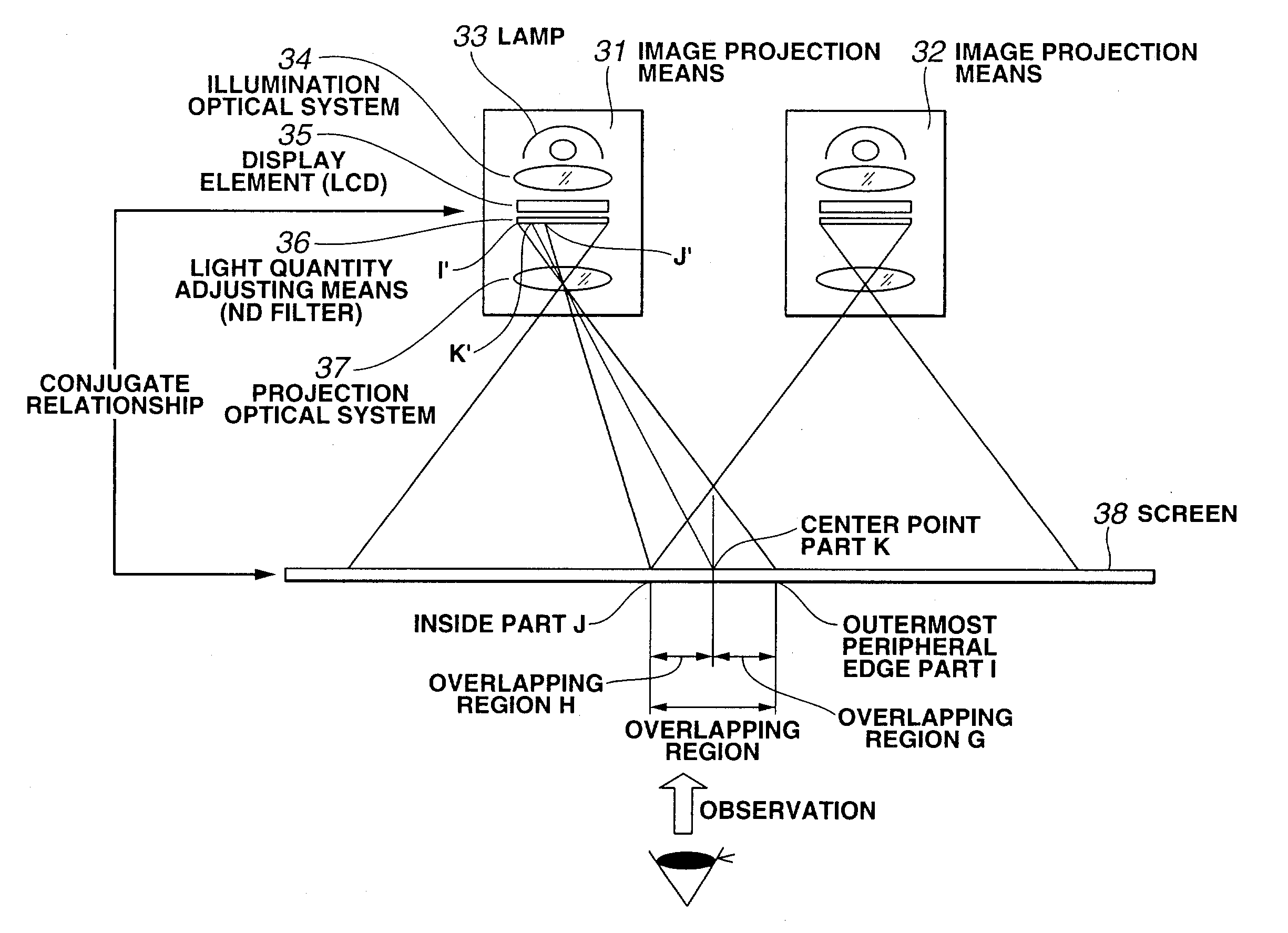
[0091] FIGS. 12 through 17 illustrate the present invention. FIG. 12 is a diagram which shows the overall construction of a multi-display device, FIGS. 13A and 13B are graphs which show how the light quantity adjusting means of the multi-display device in FIG. 12 is constructed such that there is a rectilinear light transmittance distribution, and which also show the brightness distributions of the corresponding overlapping regions, FIGS. 14A and 14B are graphs which show how the light quantity adjusting means of the multi-display device in FIG. 12 is constructed such that there is a parabolic light transmittance distribution, and which also show the brightness distributions of the corresponding overlapping regions, FIGS. 15A and 15B are graphs which show how the light quantity adjusting means of the multi-display device in FIG. 12 is constructed such that there is a light transmittance distribution consisting of a circular arc and a tangent, and which also show the brightness distr...


PUM


Abstract

The present invention provides an ND filter manufacturing method which makes it possible to obtain an ND filter film that has light transmittance information in respective positions by exposing and imaging image electronic data that has light transmittance information for respective positions used to form an ND filter by employing an exposure imaging device that is capable of the direct exposure imaging of the image electronic data, and developing the film. Furthermore, the light transmittance distributions of ND filters disposed in positions corresponding to the overlapping regions in a multi-display device are constructed from curves, so that the overlapping regions are hard to distinguish from the non-overlapping regions.

Description

[0001] This application claims benefit of Japanese Application No. 2002-046745 filed in Japan on Feb. 22, 2002, the contents of which are incorporated by this reference.[0002] 1. Field of the Invention[0003] The present invention relates to an ND filter which is prepared using an apparatus that allows direct-exposure photography of image electronic data, a method for manufacturing this ND filter, and a multi-display device and image forming device using this ND filter.[0004] 2. Description of Related Art[0005] ND filters (neutral density filters) are used in photographic systems such as cameras or the like, and are effective for performing photography in which the quantity of light is reduced without affecting the color, as in the case of photography performed under intense light or the like.[0006] Common ND filters include filters in which a light absorbing pigment is mixed with a gelatin-acetate resin, and filters in which a thin film used to absorb light is formed on a glass subs...

Claims


Application Information

Patent Timeline
IPC IPC(8): G02B5/00G03B21/00G03B21/26H04N5/74
CPCG03B21/26
Inventor YAMANAKA, KAZUYA
Owner OLYMPUS CORP
Why Eureka
Try Eureka