Low-Torque Valve and Assemblies Including Said Valve

a low-torque, valve technology, applied in the direction of diaphragm valves, engine diaphragms, operating means/releasing devices of valves, etc., can solve the problems of high cost, limited battery life, and high cost of mains electricity installation of motor-driven valves, so as to prolong the operation life of devices and reduce power and torque.

Inactive Publication Date: 2018-03-29
ZURN INDS
View PDF0 Cites 0 Cited by
  • Summary
  • Abstract
  • Description
  • Claims
  • Application Information

AI Technical Summary

Benefits of technology

[0008]Proposed herein are various designs for a low-torque valve that requires less power and torque to operate the valve which can thereby prolong the operational life of a device implementing the valve between battery changes are required. This can make the use of batteries in a motor-driven valve viable in contexts where it would be commercially unacceptable to need to replace batteries frequently (e.g., faucets, flush valves, and so forth). However, such low-torque valves could be equally powered by mains power.

Problems solved by technology

In many applications, installation of mains electricity to the motor-driven valve can be quite expensive, especially where mains power is not currently run to the physical location at which the motor-driven valve is to be used.
Unfortunately, in those situations, limited battery life provides a hard constraint on the convenience of and / or the ability to use such motor-driven valves when mains power is not a viable option.
Thus, it becomes essential to either routinely replace the batteries before they are consumed (which is highly inefficient) or to provide just-in-time replacement of batteries when they are consumed.
In either case, there are significant maintenance costs associated with monitoring and replacing batteries.
Such maintenance and cost issues associated with batteries have prevented wider adoption of battery-driven motor-driven valves for applications when use of mains power is not a viable option.

Method used


Image

  • Low-Torque Valve and Assemblies Including Said Valve
  • Low-Torque Valve and Assemblies Including Said Valve
  • Low-Torque Valve and Assemblies Including Said Valve

Examples


Embodiment Construction

[0050]Embodiments of the disclosure may be further understood with reference to the figures.

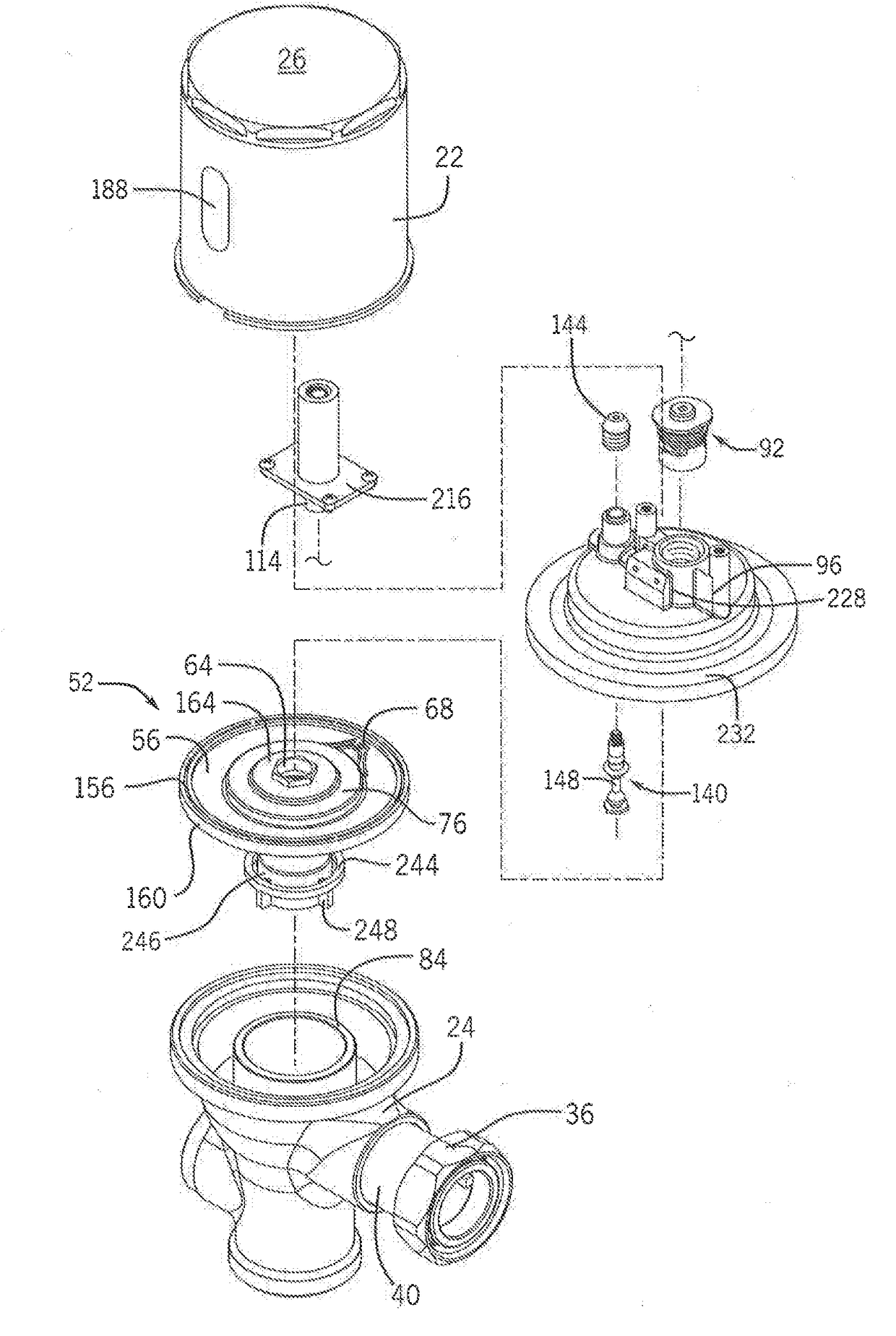
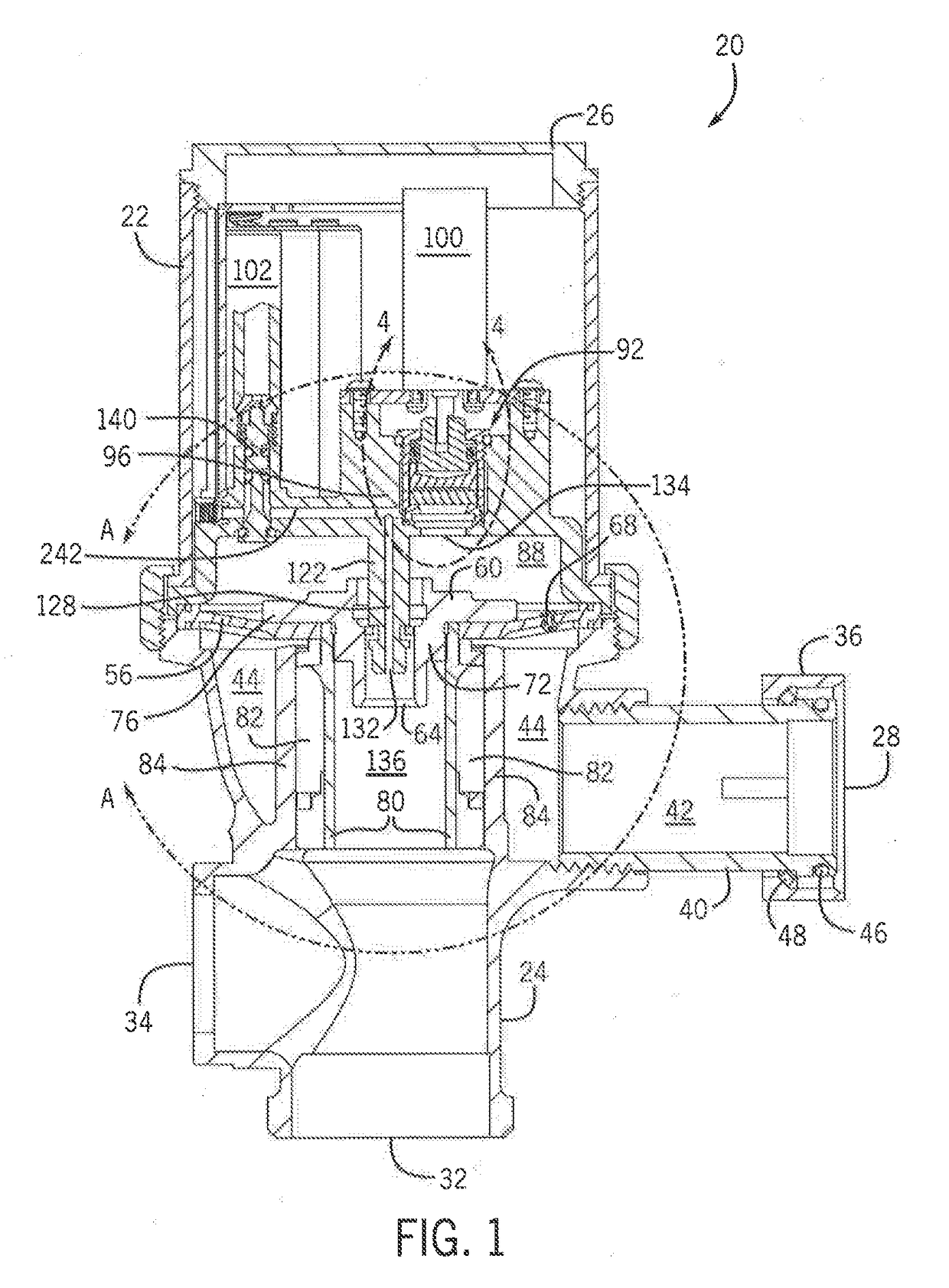
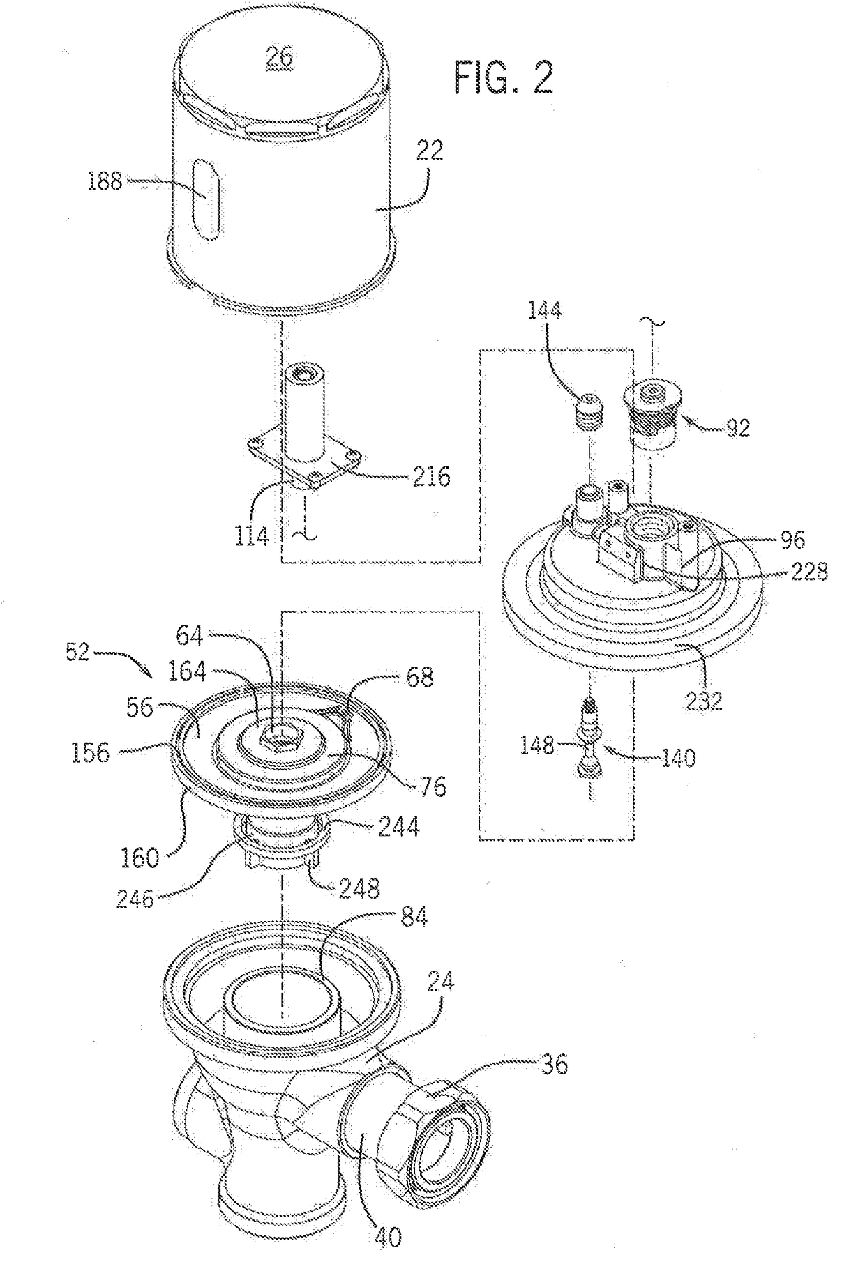
[0051]FIGS. 1 and 2 illustrate one exemplary embodiment of a flush valve assembly 20. Although a flush valve assembly is shown, it is to be appreciated that the disclosure is not limited to flush valves, flushing mechanisms, or the like.

[0052]The flush valve assembly 20 has a housing that includes an upper housing body 22 and a lower housing body 24 that may be connected such that the upper housing body 22 and lower housing body 24 enclose the flush valve assembly 20. In a non-limiting example, the upper housing body 22 may be threaded into connection with the lower housing body 24. The lower housing body 24 may have an inlet 28, an outlet 32, and a cap over an opening 34 that would traditionally accommodate a mechanical flush lever. The inlet 28 to the lower housing body 24 may connect the lower housing body 24 to a fluid source and provide fluid communication therebetween. The inlet 28 may ...


PUM


Abstract

A low-torque valve for regulating fluid flow between a valve inlet and a valve outlet is disclosed. The low-torque valve has a stationary valve element and a rotatable valve element. The stationary valve element and the rotatable valve element each may have a respective axially-facing mating surface in contact with each other. At least one opening in the rotatable valve element is rotationally positionable with respect to at least one opening in the stationary valve element between an open position and a closed position in order to regulate fluid flow from the valve inlet to the valve outlet based on an alignment of the openings of the stationary valve element and the rotatable valve element. In some forms, a torque threshold that is required to rotate the rotatable valve element into the open position from the closed position is less than 10 ounce-inches.

Description

CROSS-REFERENCE TO RELATED APPLICATIONS[0001]This application claims the benefit of U.S. Provisional Patent Application No. 62 / 399,807 filed on Sep. 26, 2016, the contents of which are incorporated by reference for all purposes as if set forth in their entirety herein.STATEMENT OF FEDERALLY SPONSORED RESEARCH OR DEVELOPMENT[0002]Not applicable.FIELD OF INVENTION[0003]This disclosure relates to a low-torque valve and the operation thereof.BACKGROUND[0004]Motor-driven valves are known for the automated operation of valves in many applications. Typically, a power source, such as mains power or a battery, selectively drives the motor to open or close the valve in the presence of some condition (e.g., a controller receives a signal that a condition has been met and the motor is driven to a particular position to alter the state of the valve).[0005]In many applications, installation of mains electricity to the motor-driven valve can be quite expensive, especially where mains power is not ...

Claims


Application Information

Patent Timeline
Patent Type & Authority Applications(United States)
IPC IPC(8): F16K5/12F16K7/12F16K31/04
CPCF16K5/12F16K7/12F16K31/041F16K31/402E03D3/06E03D3/10F16K5/0407F16K31/043
Inventor FUNARI, MICHAEL A.BLOCK, MARC G.
Owner ZURN INDS
Why Eureka
Try Eureka