
Organic electroluminescent display panel and display device

a technology of electroluminescent display panel and display device, applied in the field of display technology, can solve problems such as the visual effect of interlaced brightness

Active Publication Date: 2018-03-29
SHANGHAI TIANMA MICRO ELECTRONICS CO LTD
View PDF5 Cites 7 Cited by
  • Summary
  • Abstract
  • Description
  • Claims
  • Application Information

AI Technical Summary

Benefits of technology

The patent text describes a way to improve the display on a screen by reducing the area that can be affected by multiple light transmission regions. This helps to eliminate the visual effect of interlaced brightness and create a better display. Additionally, the text explains how arranging wires to control light emission can be more efficient by placing them in opaque emission regions that are arranged in a straight line. This reduces the length of the wires and makes it easier to dispose them in the desired locations. Overall, this method aims to improve the display's quality and appearance.

Problems solved by technology

However, existing transparent display panels may lead to a visual effect of interlaced brightness during display.

Method used


Image

  • Organic electroluminescent display panel and display device
  • Organic electroluminescent display panel and display device
  • Organic electroluminescent display panel and display device

Examples


Embodiment Construction

[0022]Reference will now be made in detail to exemplary embodiments of the invention, which are illustrated in the accompanying drawings. Wherever possible, the same reference numbers will be used throughout the drawings to refer to the same or like parts.

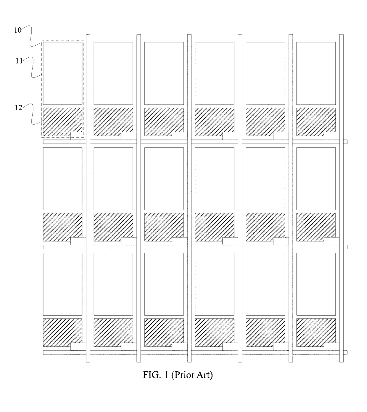
[0023]FIG. 1 illustrates a schematic view of a conventional transparent display panel. As shown in FIG. 1, the conventional transparent display panel usually includes a plurality of pixel cells 10. Each pixel cell 10 includes an opaque region for disposing a display component 12. The display component 12 is driven to emit light such that the transparent display function is achieved. Each pixel cell 10 also includes a light transmission region 11. The light transmission region 11 allows light to be transmitted through such that the scene behind the display panel can be viewed. In order to meet the requirements for arranging wires to connect the plurality of display components 12, the opaque regions corresponding to the display compo...


PUM


Abstract

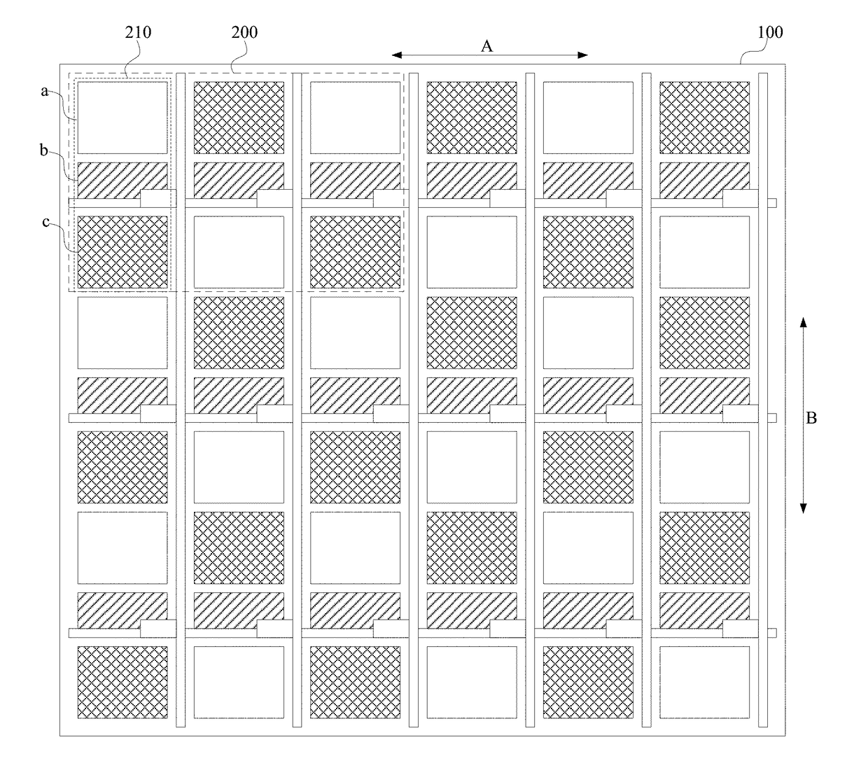
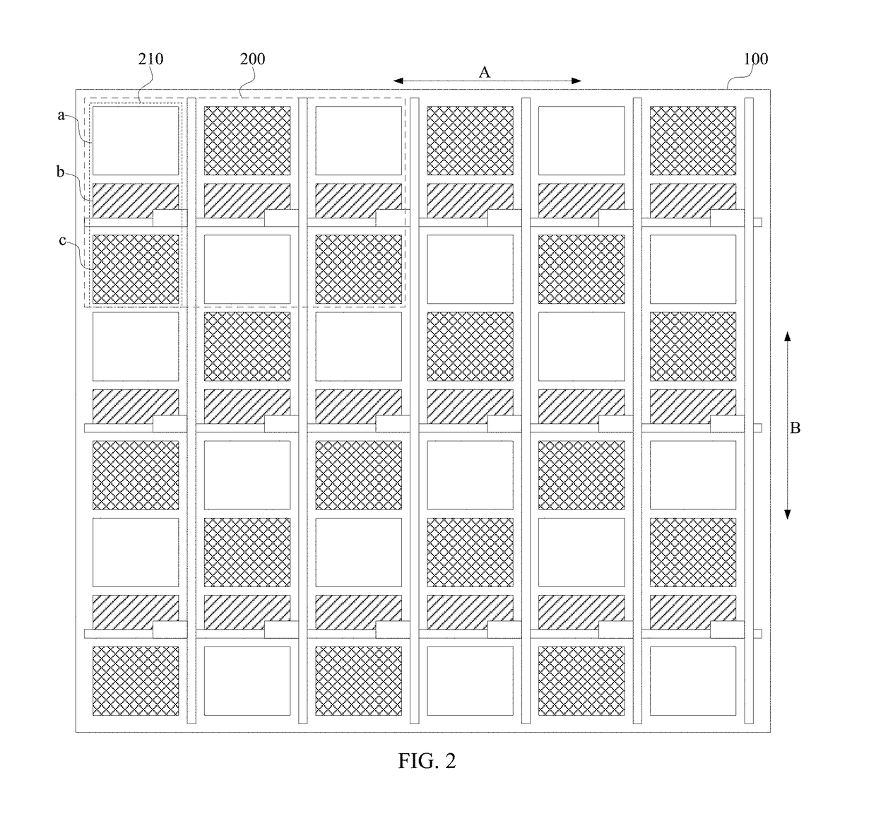
The present disclosure provides an organic electroluminescent display panel including a plurality of pixel cells arranged into a matrix on a base substrate. Each pixel cell includes at least two subpixels arranged next to each other along a first direction. Each subpixel includes a light transmission region, an opaque emission region, and an emission region arranged along a second direction with the opaque emission region being disposed between the light transmission region and the emission region. The second direction and the first direction are perpendicular to each other. For the at least two subpixels in each pixel cell, the opaque emission regions are arranged in one straight line along the first direction, the light transmission regions are arranged in two straight lines along the first direction, and the emission regions are also arranged in the two straight lines along the first direction in which the light transmission regions are arranged.

Description

CROSS-REFERENCES TO RELATED APPLICATIONS[0001]This application claims the priority of Chinese patent application No. 201710979025.4, filed on Oct. 19, 2017, the entirety of which is incorporated herein by reference.FIELD OF THE DISCLOSURE[0002]The present disclosure generally relates to the field of display technology and, more particularly, relates to an organic electroluminescent display panel and a display device.BACKGROUND[0003]As a new display technology, transparent displays can allow viewers to see the background scene behind the display screen. This newly emerging display effect expands the scope of display applications, and can be used in various display devices such as mobile phones, notebook computers, display windows, refrigerator doors, car displays, billboards, etc.[0004]However, existing transparent display panels may lead to a visual effect of interlaced brightness during display. Especially, when the pixel density, e.g. pixels per inch (PPI), is low, the visual effe...

Claims


Application Information

Patent Timeline
IPC IPC(8): G09G3/3225G09G3/20
CPCG09G3/3225G09G3/2003G09G2300/0452G09G2320/0233H10K59/353H10K59/122G09G2300/0456G09G2300/046G09G2320/0242
Inventor YING, BIANLOU, JUNHUIHE, ZESHANG
Owner SHANGHAI TIANMA MICRO ELECTRONICS CO LTD
Learn More