Muon-catalyzed controlled fusion electricity-generating apparatus and method

a technology of controlled fusion and electricity generation apparatus, which is applied in the direction of nuclear engineering, nuclear reactors, greenhouse gas reduction, etc., can solve the problems of limited viability of earth-based fusion sources, short lifetimes of muons, and energy expense of artificial generation of muons in particle accelerators

Inactive Publication Date: 2018-03-29
DREXLER JEROME
View PDF0 Cites 0 Cited by
  • Summary
  • Abstract
  • Description
  • Claims
  • Application Information

AI Technical Summary

Benefits of technology

[0010]The present invention takes advantage of the abundance of cosmic rays and generated muons on any planet or moon with a weak (or no) magnetic field and a thin atmosphere, as well as in planetary or lunar orbit or interplanetary space, to catalyze fusion events. The cosmic rays and muons are available here for free and do not need to be generated artificially in an accelerator. Fusion material will interact with the flux of cosmic rays and muons such that some combination of particle-target fusion and / or muon-catalyzed fusion will take place. One cosmic ray particle can generate hundreds of muons, and each muon can typically catalyze about 100 fusion reactions before it decays (the exact number depending on the muon “sticking” cross-section to any helium fusion products). Additionally, any remaining cosmic rays can themselves directly stimulate a fusion event by particle-target fusion, wherein the high energy cosmic ray particles (mostly protons, but also helium nuclei) bombard relatively stationary target material.

Problems solved by technology

The energy expense of generating muons artificially in particle accelerators combined with their short lifetimes has limited its viability as an earth-based fusion source, since it falls short of break-even potential.
Although some fusion events can be observed with as little as 10 KeV acceleration, fusion cross-sections are sufficiently low that accelerator-based particle-target fusion are inefficient and fall short of break-even potential.

Method used


Image

  • Muon-catalyzed controlled fusion electricity-generating apparatus and method
  • Muon-catalyzed controlled fusion electricity-generating apparatus and method
  • Muon-catalyzed controlled fusion electricity-generating apparatus and method

Examples


Embodiment Construction

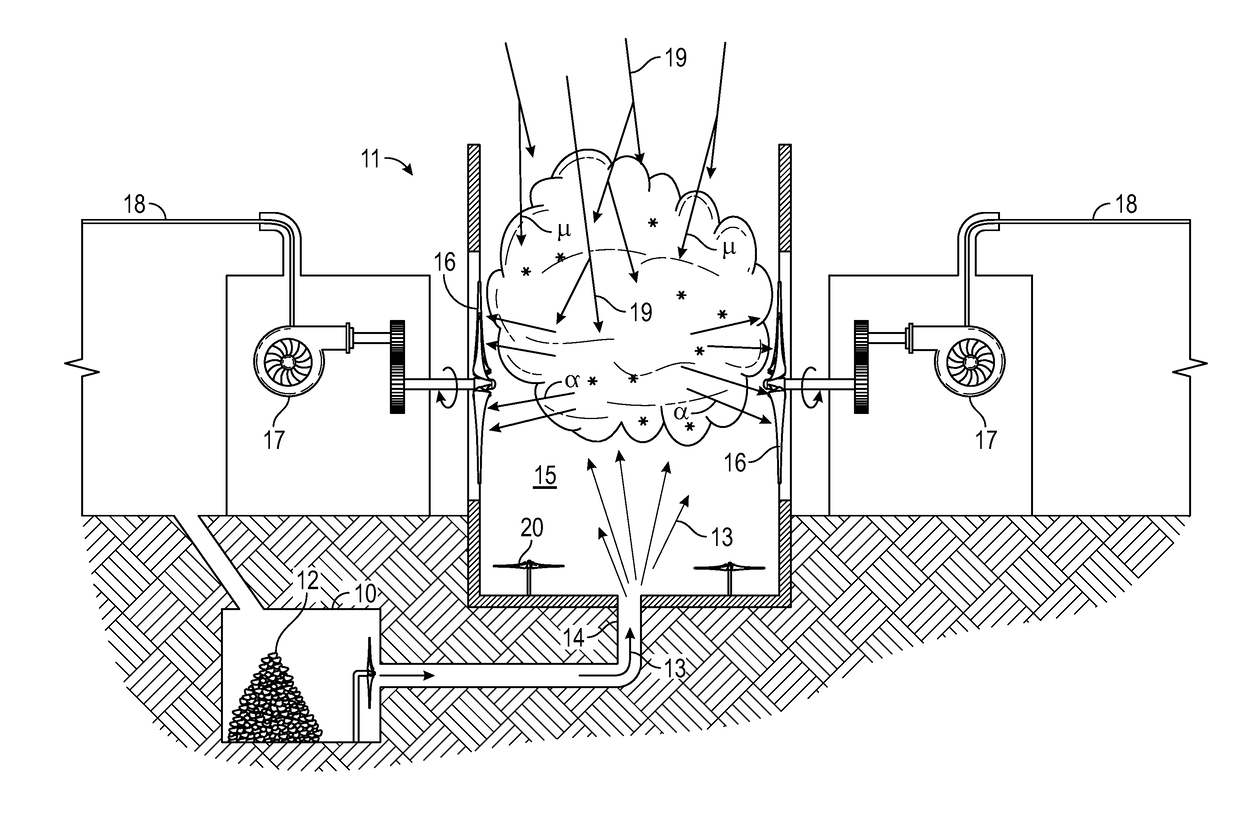
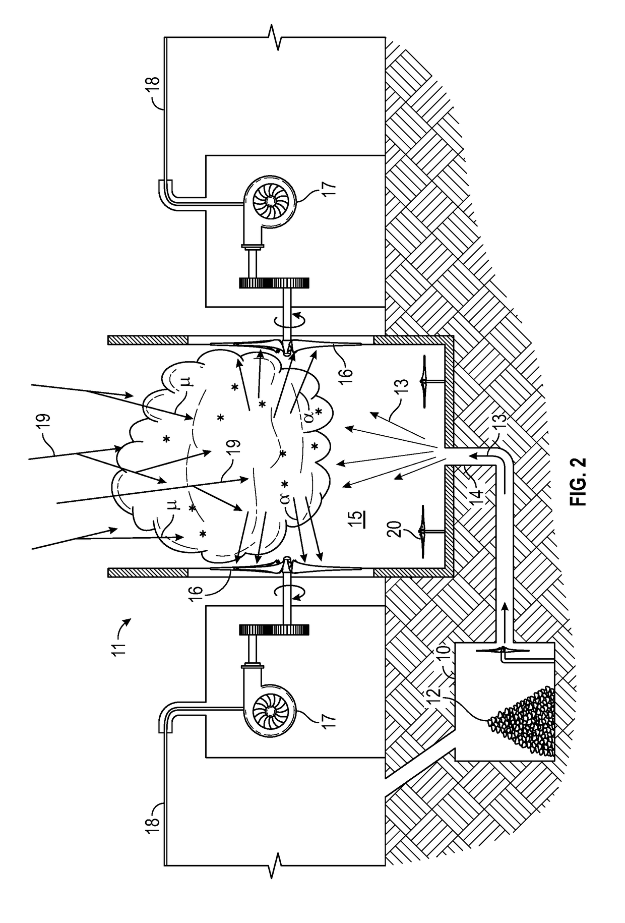
[0017]FIG. 1 shows a turbine electric generator apparatus 11 located outside of an arrangement of habitats 22 and 25 on a planetary or lunar surface, where generators are powered by reaction of ambient cosmic rays and muons with a dispersed cloud of micro-fusion fuel within a reaction volume of the apparatus 11. Electrical power lines 18 lead from the generator apparatus 11 to the various habitats. Some habitats might be underground, as in habitat 22, which might be accessible via a stairwell 23. Electrical power lines 18 could feed electricity to the habitat 22 via conduits along the same access column that supports the stairwell. Other habitats might be above ground, as in habitat 25, powered by electricity supplied via external power lines 18. In accord with the invention, the generator apparatus 11 has turbines driven by fast helium nuclei micro-fusion products generated from dispersed lithium-6 deuteride or other deuterium-containing micro-fusion target material exposed to the ...


PUM


Abstract

A turbine generator for producing electricity is described for use on planets and moons, or corresponding planetary or lunar orbits, where magnetic fields and atmospheres are sufficient low to obtain an adequate ambient flux of cosmic rays and muons for useful micro-fusion. A source of deuterium-containing micro-fusion particle fuel material is supplied via a flue to a columnar reaction volume, where it is dispersed and interacts with incoming cosmic rays and muons. Nuclear micro-fusion products (energetic alpha particles) drive a set of helium-wind turbines arranged around the reaction volume. Electrical generators coupled to the turbines generate electricity to supply nearby habitats and equipment.

Description

CROSS-REFERENCE TO RELATED APPLICATION[0001]This application claims priority under 35 U.S.C. 119(e) from prior U.S. provisional application 62 / 398,710 filed Sep. 23, 2016.TECHNICAL FIELD[0002]The present invention relates to generation of electric power, and in particular to methods and apparatus employing muon-catalyzed nuclear fusion for use in interplanetary space and on surfaces of the Moon, Mars and other planets or moons with little or no magnetic field and / or atmosphere.BACKGROUND ART[0003]Muon-catalyzed fusion was observed by chance in late 1956 by Luis Alvarez and colleagues during evaluation of liquid-hydrogen bubble chamber images as part of accelerator-based particle decay studies. These were rare proton-deuteron fusion events that only occurred because of the natural presence of a tiny amount of deuterium (one part per 6400) in the liquid hydrogen. It was quickly recognized that fusion many orders of magnitude larger would occur with either pure deuterium or a deuterium...

Claims


Application Information

Patent Timeline
Patent Type & Authority Applications(United States)
IPC IPC(8): G21D7/00H02K7/18G21B1/19G21D1/02
CPCG21D7/00G21D1/02G21B1/19H02K7/1823G21B3/004G21D1/00Y02E10/72Y02E30/00Y02E30/10Y02E30/30
Inventor DREXLER, JEROME
Owner DREXLER JEROME
Why Eureka
Try Eureka