Enhancements to phase-noise compensation reference signal design and scrambling

a reference signal and phasenoise compensation technology, applied in the field of wireless communication, can solve the problems of increasing scheduling overhead, interference affecting the transmission of wireless communications systems, and receivers being unable to efficiently receive reference signals

Active Publication Date: 2018-03-29
QUALCOMM INC
View PDF3 Cites 88 Cited by
  • Summary
  • Abstract
  • Description
  • Claims
  • Application Information

AI Technical Summary

Benefits of technology

[0004]In some cases, transmissions in a wireless communications system may be impacted by interference. As a result, a receiver, such as a UE, may use reference signals to mitigate interference. Depending on a location of the reference signals within wireless resources, however, a receiver may be unable to efficiently receive the reference signals due to interference with tones within the resources. Some receivers may be able to use reference signals assigned to other receivers. However, transmitting additional information to enable this reference signal sharing may significantly increase scheduling overhead and create additional problems. Thus, communication efficiency within the wireless communications system may benefit from techniques that enable coherent scheduling of reference signals and improve flexibility for reference signal reception at a receiver.SUMMARY

Problems solved by technology

In some cases, transmissions in a wireless communications system may be impacted by interference.
Depending on a location of the reference signals within wireless resources, however, a receiver may be unable to efficiently receive the reference signals due to interference with tones within the resources.
However, transmitting additional information to enable this reference signal sharing may significantly increase scheduling overhead and create additional problems.

Method used


Image

  • Enhancements to phase-noise compensation reference signal design and scrambling
  • Enhancements to phase-noise compensation reference signal design and scrambling
  • Enhancements to phase-noise compensation reference signal design and scrambling

Examples


Embodiment Construction

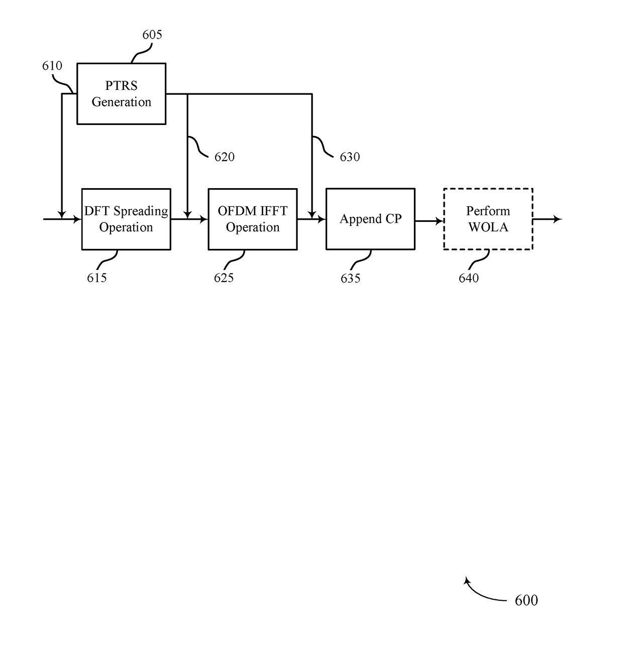
[0040]The described techniques relate to improved methods, systems, devices, and apparatuses that support enhancements to phase-noise compensation reference signals (PCRS) design and scrambling. Generally, the described techniques provide for identification of a DC tone, which may influence transmissions of PCRS (e.g., which may alternatively be referred to as phase-noise tracking reference signals, phase tracking reference signals, or PTRS). It is to be understood that, though described in the context or PTRS collision avoidance, the DC tone indication may be used for other purposes (e.g., multi-user scheduling) without deviating from the scope of the present disclosure.

[0041]As an example, transmitting PTRS to avoid collisions with the DC tone may enable improved reception of PTRS by a base station or a UE. In one example, multiple PTRS may be transmitted using sets of resource blocks (RBs), where a frequency for each PTRS within the sets of RBs is different from a frequency corre...


PUM


Abstract

Methods, systems, and devices for wireless communication are described. In one example, phase-noise compensation tracking signals (PTRS) may be transmitted using sets of resource blocks (RBs), where a frequency for each PTRS within the sets RBs is different from a frequency corresponding to a direct current (DC) tone. In another example, a time-domain-based PTRS may be used, where a discrete Fourier transform (DFT)-spread-orthogonal frequency division multiplexing (DFT-s-OFDM) symbol may include a cyclic prefix and a PTRS inserted in the DFT-s-OFDM symbol. Additionally or alternatively, a guard-interval-based DFT-s-OFDM symbol may include a PTRS that replaces part or all of a guard interval. In some examples, subsets of tones used for PTRS across a system bandwidth may be transmitted using a scrambled modulation symbol, where at least one antenna port may be used for the transmission of PTRS.

Description

CROSS REFERENCES[0001]The present application for patent claims priority to U.S. Provisional Patent Application No. 62 / 401,049 by Akkarakaran, et al., entitled “Enhancement To Phase-Noise Compensation Reference Signal Design and Scrambling,” filed Sep. 28, 2016, assigned to the assignee hereof, and which is expressly incorporated by reference herein.INTRODUCTION[0002]The following relates generally to wireless communication, and more specifically to enhancements to phase-noise compensation reference signal design and scrambling.[0003]Wireless communications systems are widely deployed to provide various types of communication content such as voice, video, packet data, messaging, broadcast, and so on. These systems may be capable of supporting communication with multiple users by sharing the available system resources (e.g., time, frequency, and power). Examples of such multiple-access systems include fourth generation (4G) systems such as a Long Term Evolution (LTE) systems or LTE-A...

Claims


Application Information

Patent Timeline
Patent Type & Authority Applications(United States)
IPC IPC(8): H04L27/26G01S13/34
CPCH04L27/2636G01S13/346H04L27/2628H04L5/0007H04B7/0413H04L27/2605H04L27/2613H04L27/26134H04L5/0053H04L5/0048H04W28/0236
Inventor AKKARAKARAN, SONYLUO, TAO
Owner QUALCOMM INC
Why Eureka
Try Eureka