Screw

a screw and screw body technology, applied in the field of screw, can solve the problems of not being able to accurately maintain the distance, not being able to use filigree universal joints, and not being able to achieve accurate distance maintenance, etc., to achieve the effect of changing the flexibility and the length of the flexible joint part, and compact setup

Active Publication Date: 2018-04-05
BLUEWATER MEDICAL GMBH
View PDF47 Cites 10 Cited by
  • Summary
  • Abstract
  • Description
  • Claims
  • Application Information

AI Technical Summary

Benefits of technology

[0017]To attain a particularly compact setup, it is proposed for the coupling to be positively connected to head part and threaded part. This makes it possible to already obtain a certain flexibility at the joint location between head part and threaded part.
[0018]The coupling preferably has a plurality of elements, which are positively connected to one another. This makes it possible to change the flexibility and the length of the flexible joint part in a simple manner by means of the number of elements. The elements thereby preferably have the same shape or two elements of different shapes alternate.

Problems solved by technology

Even though the elastic joint provides the screw with a certain axial elasticity, a transmission of torques is not possible without using the special socket key.
In the case of a universal joint, the filigree universal joint is not possible for the transmission of larger torques and tensile forces with small shaft diameters.
In one embodiment, WO 2006 105935 A1 allows only one bending movement and even though the other exemplary embodiments allow for a plurality of bending movements, the screw is then so elastic in its longitudinal extension that it does not make it possible any longer to be able to accurately maintain the distance of the bones relative to one another and to transmit a torque from the head part to the threaded part.
In the case of all embodiments, the possibility of an offset between head part and threaded part is gained with an inaccurate transmission of the torque between head part and threaded part.

Method used


Image

  • Screw
  • Screw
  • Screw

Examples


Embodiment Construction

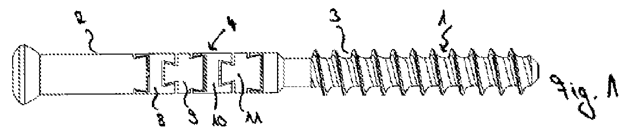
[0041]The screw 1 shown in FIG. 1 has a head part 2 and a threaded part 3. As flexible joint part 4, provision is made between the head part 2 and the threaded part 3 for a combination of a first coupling element 5 with a plug-in connector 6 for transmitting torsional forces, and a second coupling element 7 for transmitting torsional forces. In the axial direction between head part 2 and threaded part 3, the first coupling element 5 of the flexible joint part 4 consists of 4 joint elements 8, 9, 10 and 11, which are arranged one behind the other.

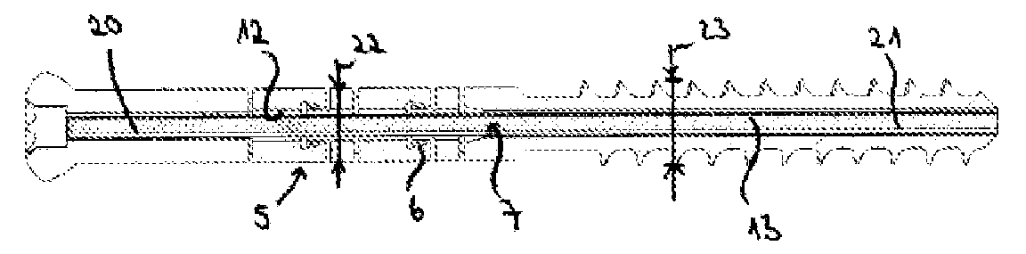
[0042]The first coupling element 5 with the joint elements 8 to 11 has a central bore 12, which makes it possible to arrange a flexible wire inside the first coupling element 5 as second coupling element 7. This wire 13 is fixedly connected to the head part 2 and the threaded part 3 and thus allows the transmission of tensile forces between head part 2 and threaded part 3, while the wire only offers a very small resistance to torsional force...


PUM


Abstract

A screw includes a head part, a threaded part and a flexible connector between the head part and the threaded part for transmitting a torsional force between the head part and the threaded part, and to allow two bending movements between the head part and the threaded part in the opposite direction in the longitudinal axis of the screw, wherein the head part and the threaded part in each case have a longitudinal axis, which can be arranged offset in parallel to one another, and wherein the screw has an ε-module of between 20,000 and 100,000 N/mm2 against a rotation in the case of an arrangement of the head part and the threaded part on a longitudinal axis.

Description

CROSS REFERENCE TO RELATED APPLICATIONS[0001]Applicant claims priority under 35 U.S.C. § 119 of German Application No. 10 2016 011 947.0 filed Oct. 5, 2016, the disclosure of which is incorporated by reference.BACKGROUND OF THE INVENTION1. Field of the Invention[0002]The invention relates to a screw comprising a head part, a threaded part and a flexible connector between head part and threaded part. The fixation of two bones at a fixed distance to one another, while simultaneously maintaining the mobility of the bones to one another, for example for bridging a joint gap, is the object of the screw. The demand on the screw is to be able to absorb tensile forces, which are as high as possible, and to thereby simultaneously offer the least possible resistance to a displacement of the bones (at right angles to the tensile direction) and to thereby be able to develop a sufficiently high torque to be able to be screwed into the bone and also out of the bone again.2. Description of the Rel...

Claims


Application Information

Patent Timeline
Patent Type & Authority Applications(United States)
IPC IPC(8): A61B17/86
CPCA61B17/8685A61B17/863A61B17/864A61B17/683A61B2017/0069A61B17/8869A61B2017/00862F16B31/04Y10S411/916
Inventor LUTZ, CHRISTIAN
Owner BLUEWATER MEDICAL GMBH
Why Eureka
Try Eureka