Sealing Gasket with Corrugated Insert for Sealing Restrained or Non-Restrained Plastic Pipelines

a technology of corrugated inserts and sealing gaskets, which is applied in the direction of engine seals, sleeve/socket joints, pipe joints, etc., can solve the problems of separation of two elements, critical limitations of each solution, and the inability to provide all the needed sealing

Active Publication Date: 2018-04-05
S & B TECHN PRODS
View PDF36 Cites 15 Cited by
  • Summary
  • Abstract
  • Description
  • Claims
  • Application Information

AI Technical Summary

Benefits of technology

[0013]Another object of the invention is to provide a reinforcing element that is not required to be bonded to the rubber element, hence creating the possibility of being made from a multitude of materials.
[0014]Another object of the invention is to provide such a sealing gasket with special reinforcing attributes which allow it to seal under a variety of pressure conditions without being twisted or extruded, or displaced during field assembly, and yet which can be installed by hand in the bell raceway.

Problems solved by technology

Each of these solutions had critical limitations.
The plastic region in some cases, reduced the rubber surface contact area, sometimes leading to problems in providing the needed sealing in all conditions, including high pressure, low pressure and cyclic surges.
Poor bonding resulted in separation of the two elements.
The reinforcing band was subject to being misplaced and breakage in the two part system.
Thus, in some cases, the prior art solutions failed to provide the needed joint integrity, often contributing to the complexity and expense of the manufacturing operation and field installation.
As a result, the metal insert design did not take into account shrinkage of the injected rubber during curing.
Since the insert design does not take into account this shrinkage and given the final product dimensions, the insert may not fit properly in the enlarged injection cavity.
This conflict makes it difficult to achieve the desired product dimensions.
The conflict between the insert dimensions and rubber shrinkage during the molding operation is particularly problematic in the case of plastic inserts.
However, the nature of the succession of thin and thick sections could produce problems in injection molding.
Also, if the insert cannot stretch to fit in the expanded mold cavity, rubber shrinkage over a non-shrinking insert can produce different shrinkage in different directions and make the resulting shrinkage difficult to predict.

Method used


Image

  • Sealing Gasket with Corrugated Insert for Sealing Restrained or Non-Restrained Plastic Pipelines
  • Sealing Gasket with Corrugated Insert for Sealing Restrained or Non-Restrained Plastic Pipelines
  • Sealing Gasket with Corrugated Insert for Sealing Restrained or Non-Restrained Plastic Pipelines

Examples


Embodiment Construction

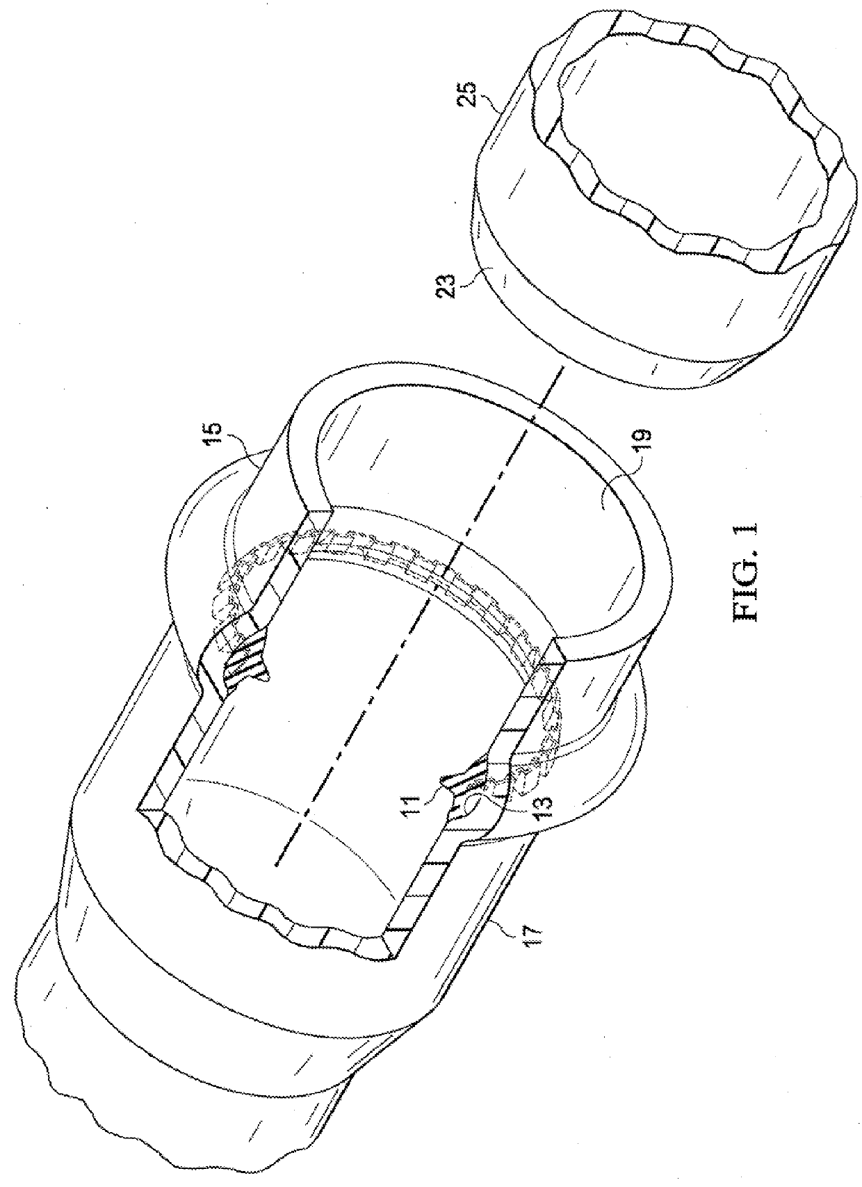
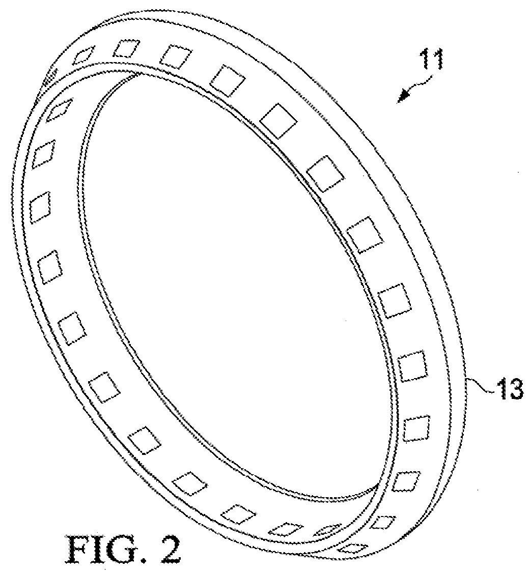
[0039]Turning now to the attached illustrations, FIG. 1 shows the gasket 11 of the invention in place prior to the assembly of a pipe joint. The gasket 11 is installed within a groove or raceway 13 provided within the belled end 15 of a female pipe section of thermoplastic pipe 17. The female pipe section 17 can be formed of any of a variety of commercially available thermoplastic materials, such as the polyolefin family including polyethylene and polypropylene as well as polyvinyl chloride and similar materials. As has been mentioned, thermoplastic pipes of this general type are used in a variety of industrial settings including water, sewage and chemical industries. The female, belled end 15 of the thermoplastic pipe section has a mouth opening 19 which is engageable with a male spigot end 23 of a mating male pipe section 25 to form a pipe joint. The gasket receiving raceway 13 has been pre-formed in the pipe mouth opening 19 at the pipe manufacturing facility, as by using a colla...


PUM


Abstract

A pipe sealing gasket is shown which is designed to be received within a raceway provided within a socket end of a female bell plastic pipe end which is assembled with a mating male spigot pipe end to form a plastic pipe joint. The raceway in the female bell plastic pipe end is preformed during manufacture and the gasket is installed thereafter. The gasket has a rubber body portion which is reinforced by a hard corrugated ring-shaped insert. The hard corrugated ring-shaped insert acts to prevent extrusion of the gasket during a variety of pressure conditions as well as preventing displacement during field assembly.

Description

CROSS REFERENCE TO RELATED APPLICATIONS[0001]The present application claims priority from a previously filed provisional application Ser. No. 62 / 402,352, filed Sep. 30, 2016, entitled “Sealing Gasket With Corrugated Insert For Sealing Restrained or Non-Restrained Plastic Pipelines”, by the same inventor.BACKGROUND OF THE INVENTION1. Field of the Invention[0002]The present invention relates generally to sealing gaskets and sealing systems used for pipe joints in plastic pipelines in which a male spigot pipe section is installed within a mating female socket pipe section to form a pipe joint. In some cases, the sealing gasket also acts as a part of a restrained joint system for the pipe joint.2. Description of the Prior Art[0003]Fluid sealing systems for plastic, fluid conveying pipes are used in a variety of industries. The pipes used in such systems are typically formed from thermoplastic materials including polyolefins and PVC. In forming a joint between sections of pipe, the spigo...

Claims


Application Information

Patent Timeline
Patent Type & Authority Applications(United States)
IPC IPC(8): F16L21/03F16J15/12
CPCF16J15/121F16L21/03F16L21/08F16L37/0845
Inventor QUESADA, GUIDO
Owner S & B TECHN PRODS
Why Eureka
Try Eureka