Electric power tool and method of assembling electric power tool

Inactive Publication Date: 2018-04-12
MAKITA CORP
View PDF2 Cites 6 Cited by
  • Summary
  • Abstract
  • Description
  • Claims
  • Application Information

AI Technical Summary

Benefits of technology

[0018]The housing may include a vibrating section, and a vibration-insulated section. The load detector may be disposed in the vibrating section. The vibrating section houses the hammer part and vibrates in response to the drive of the motor. The vibration-insulated section receives a reduced vibration transmitted from the vibrating section. This configuration can help facilitate detection of vibration of the housing by the load detector and improve the precision of detection of a load on the tool bit.
[0019]The load detector may be rigidly coupled to the housing in the vibrating section. This configuration helps facilitate transmission of vibration of t

Problems solved by technology

In the aforementioned electric power tools, it may be difficult to place the sensor unit, which is configured integrally with the motor control unit, in the optimal location.
In addition, it may also be difficult to effectively utilize the inner space (in other words, inside a housi

Method used


Image

  • Electric power tool and method of assembling electric power tool
  • Electric power tool and method of assembling electric power tool
  • Electric power tool and method of assembling electric power tool

Examples


Embodiment Construction

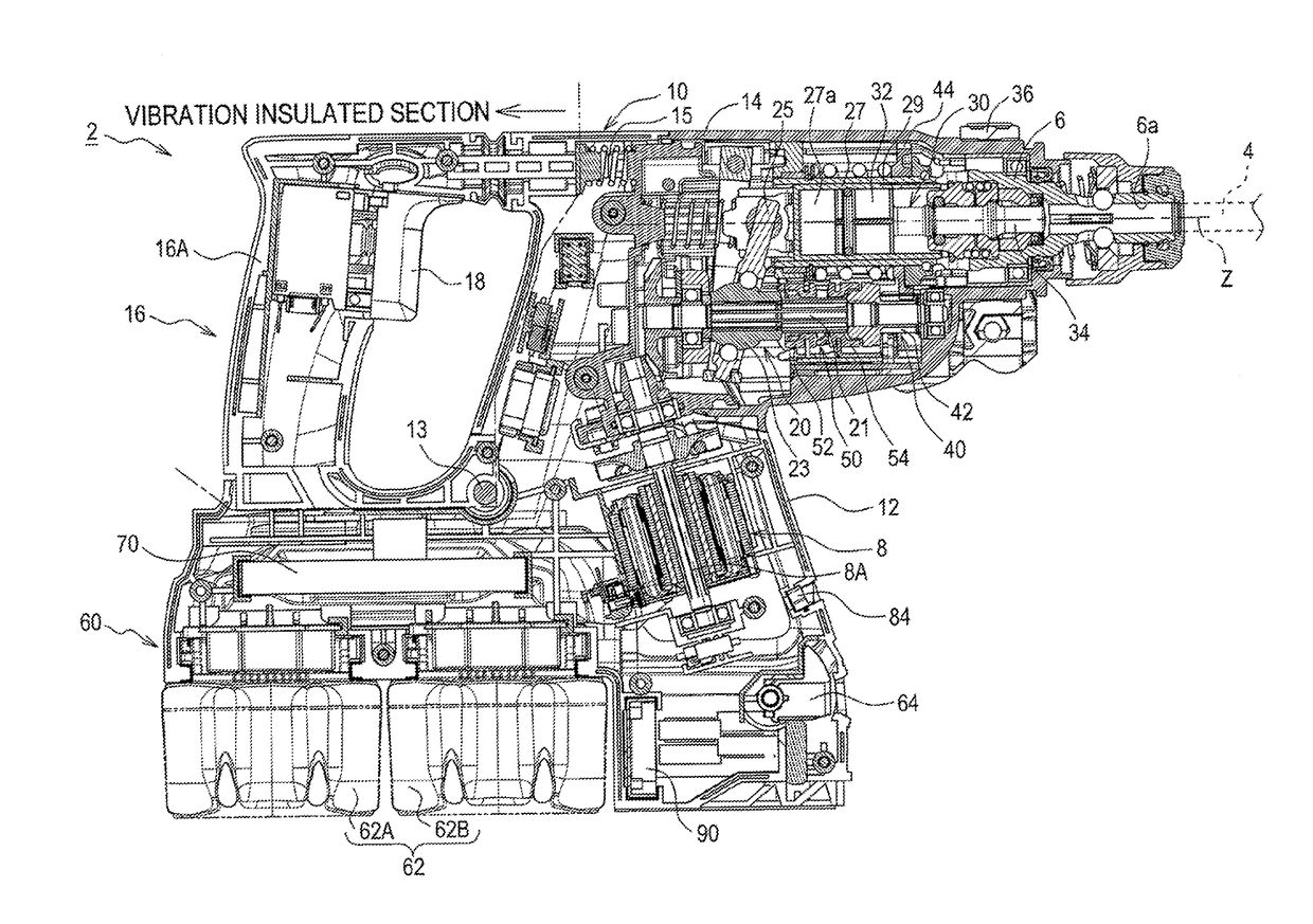
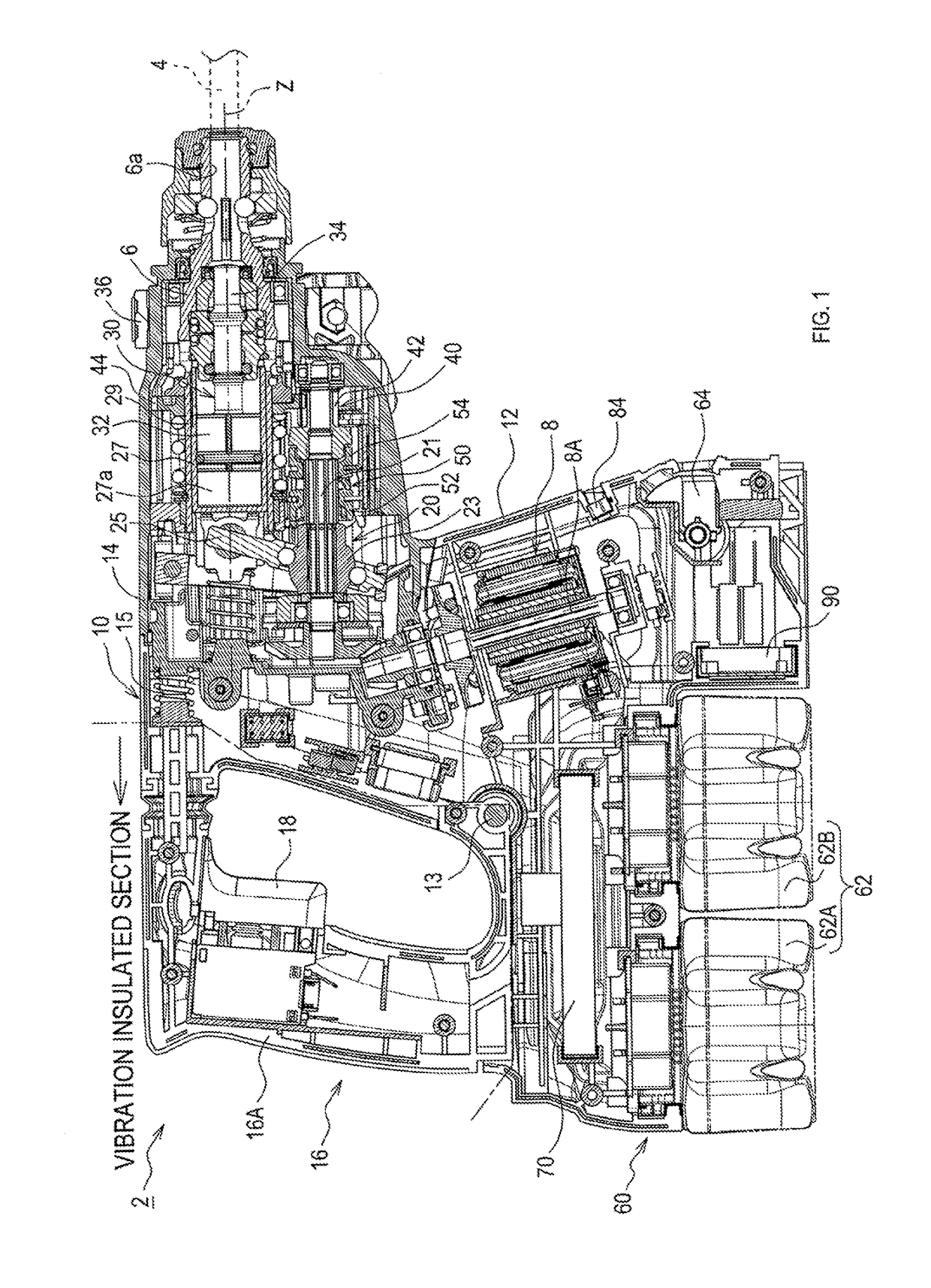
[0037]A hammer drill 2 in the present embodiment is configured to perform chipping work or drilling work on a workpiece (for example, on concrete) with a tool bit 4 such as a hammer bit, by moving the tool bit 4 in a hammering motion along the longitudinal axis of the tool bit 4, or in a rotational motion about the longitudinal axis of the tool bit 4, for example.

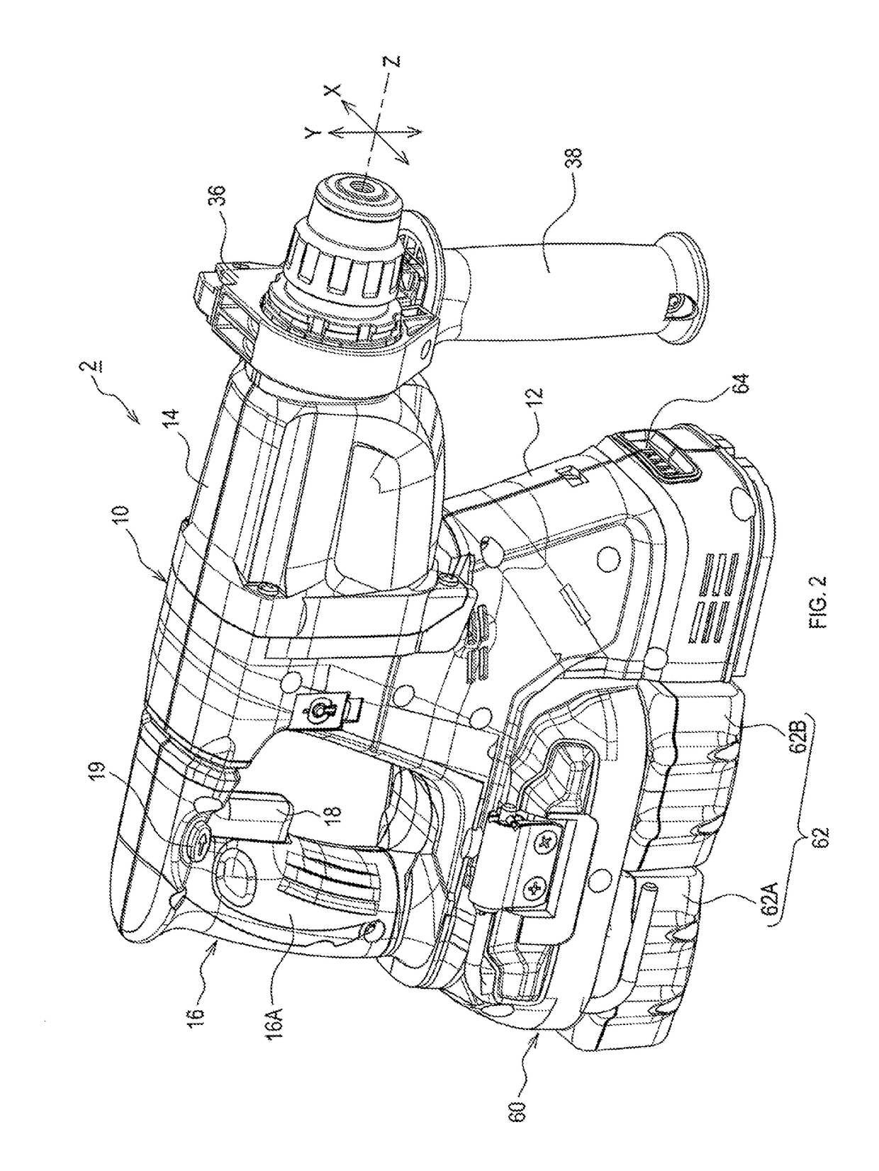
[0038]As shown in FIG. 1, the hammer drill 2 includes a main housing 10 that defines the outline of the hammer drill 2. At the tip area of the main housing 10, the tool bit 4 is detachably attached to the main housing 10 via a tool holder 6. The tool holder 6 has a tubular shape and functions as an output shaft.

[0039]The tool bit 4 is inserted through a bit hole 6a of the tool holder 6 and held by the tool holder 6. The tool bit 4 can be moved in a reciprocating motion, relative to the tool holder 6, along the longitudinal axis of the tool bit 4. A rotational motion of the tool bit 4, relative to the tool holder 6, about th...


PUM


Abstract

An electric power tool in one aspect of the present disclosure includes a housing; a motor; an output shaft; a rotation transmission; a motor controller; and a twisted-motion detector. The twisted-motion detector is disposed in the housing independently from the motor controller. The twisted-motion detector detects a twisted-motion of the housing in the circumferential direction of the output shaft and outputs a result of the detection to the motor controller.

Description

CROSS-REFERENCE TO RELATED APPLICATIONS[0001]This application claims the benefit of Japanese Patent Application No. 2016-199176 filed Oct. 7, 2016 in the Japan Patent Office, the disclosure of which is incorporated herein by reference.BACKGROUND[0002]The present disclosure relates to an electric power tool.[0003]Electric power tools disclosed in Japanese Unexamined Patent Application Publications 2004-518551 and 2013-244581 detect a locked-state, in which a tip tool cannot be controlled, by a device such as an acceleration sensor. These electric power tools stop the drive of a motor when the locked-state is detected. In these electric power tools, a sensor unit is configured integrally with a motor control unit.SUMMARY[0004]In the aforementioned electric power tools, it may be difficult to place the sensor unit, which is configured integrally with the motor control unit, in the optimal location. In addition, it may also be difficult to effectively utilize the inner space (in other w...

Claims


Application Information

Patent Timeline
IPC IPC(8): B25F5/02B25D17/04B25F5/00
CPCB25F5/02B25D17/04B25F5/006B25D2250/201B25D2250/165B25D2250/221B25D2216/0023B25D16/00B25D2211/068
Inventor SUNABE, HIKARUYAMAMOTO, HIROKATSUUMEMOTO, RYO
Owner MAKITA CORP
Why Eureka
Try Eureka