A low energy building

a low-energy building and building technology, applied in the direction of lighting and heating equipment, electrical equipment, luminescence, etc., can solve the problems of unnecessary expense, low efficiency, and high consumption of power, and achieve the effect of controlling cooling

Inactive Publication Date: 2018-04-12
X TEC PTY LTD
View PDF7 Cites 0 Cited by
  • Summary
  • Abstract
  • Description
  • Claims
  • Application Information

AI Technical Summary

Benefits of technology

[0038]The method may involve cooling the polymer and / or photoluminescence. The cooling may be controlled.

Problems solved by technology

Commercial buildings such as factories and office buildings are typically filled with powered fluorescent tubes which consume power.
In practice, the lights are often needlessly left activated after hours which is not only an unnecessary expense, but also harmful to the environment.

Method used


Image

  • A low energy building
  • A low energy building
  • A low energy building

Examples


Embodiment Construction

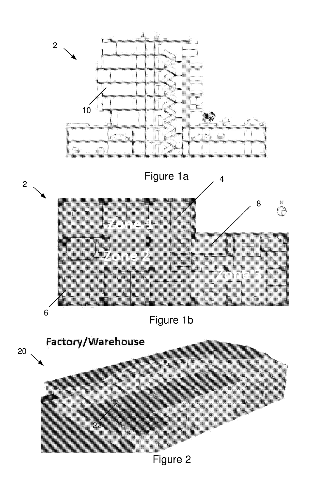
[0071]According to an embodiment of the present invention, there is provided a low-energy office building 2 as shown in FIG. 1. The multi-storey building 2 includes a distributed power supply which supplies mains voltage to lights spread throughout the building 2. The distributed power supply includes a mains power supply (e.g. 115V or 240V), a battery storage system, and solar cells mounted on the roof of the building 2 to charge the battery. The building 2 further includes a lighting system 100 for being powered by the distributed power supply and as described in detail below.

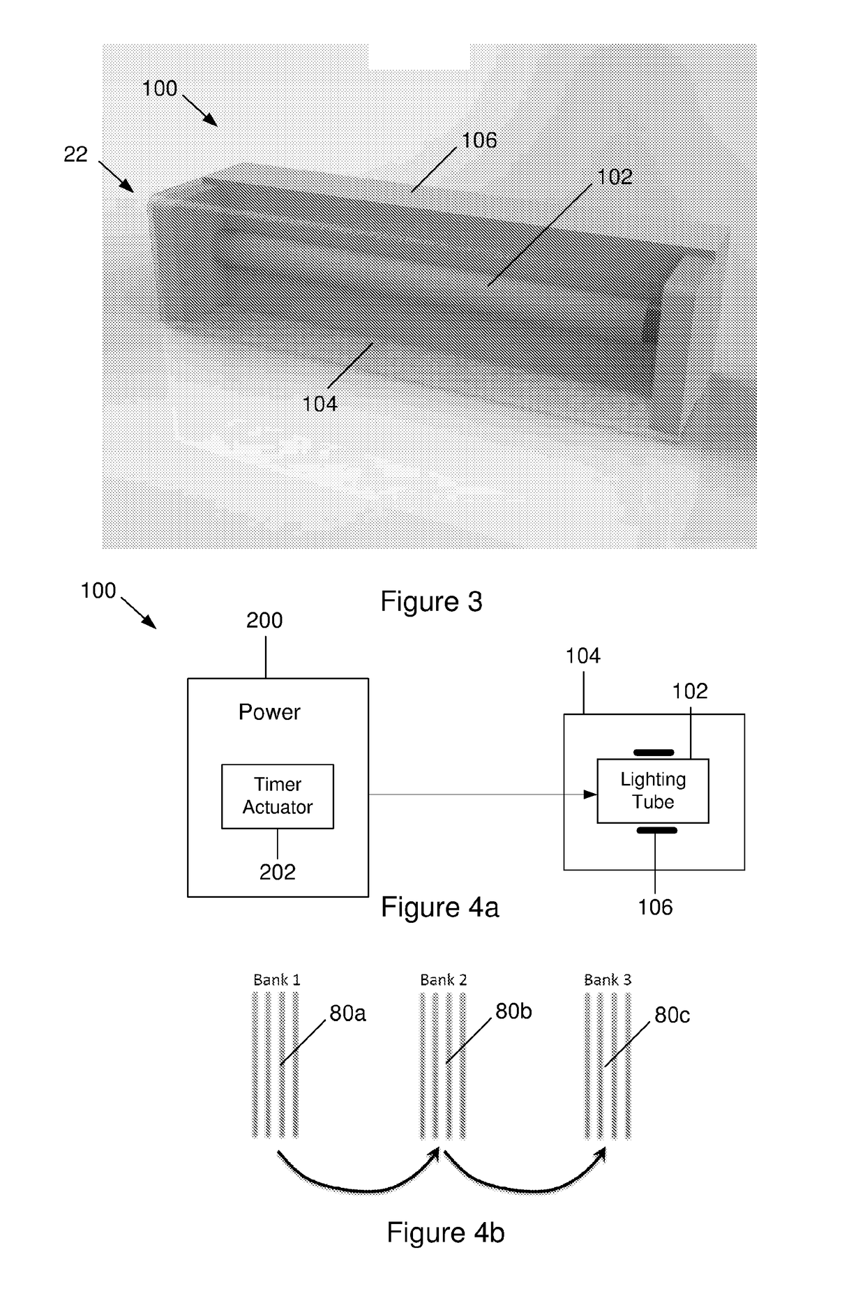
[0072]Turning to FIG. 1b, the lighting system 100 includes many distributed lights that are arranged in zones 4, 6, 8 within the building 2. Each zone 4, 6, 8 relates to a portion of a given floor 10 (FIG. 1a) of the building 2. The building 2 includes an actuator 202, described in detail below, and for actuating the lights 102 in the zones 4, 6, 8 at intervals.

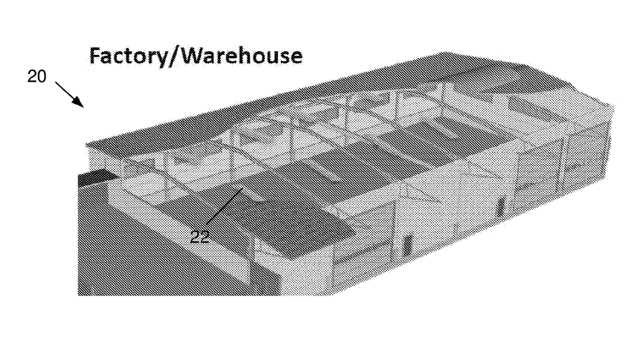
[0073]As shown in FIG. 2, another embodiment of ...


PUM


Abstract

The present invention relates to a building. The building includes a distributed power supply and a lighting system for being powered by the distributed power supply. The system includes distributed lights for being coupled to the distributed power supply. Covers are provided for covering respective lights. Photoluminescence is borne by each cover. Advantageously, the light charges the photoluminescence borne by the cover. In turn, the cover passively discharges and provides passive illumination in the dark by virtue of the photoluminescence. The building lighting system provides illumination for after-hours personnel in the building after the light is turned off, or in the event of a power disruption when a backup power generator is not present.

Description

TECHNICAL FIELD[0001]The present invention generally relates to a low energy building within a low-energy building lighting system. The present invention has particular application to commercial buildings such as factories and office buildings having large numbers of distributed lights.BACKGROUND[0002]The reference to any prior art in this specification is not, and should not be taken as an acknowledgement or any form of suggestion that the prior art forms part of the common general knowledge.[0003]A fluorescent tube is a low pressure mercury-vapor gas-discharge lamp that uses fluorescence to produce visible light.[0004]Commercial buildings such as factories and office buildings are typically filled with powered fluorescent tubes which consume power. These buildings often remain at least in part illuminated after hours for security, or to assist after-hours personnel such as cleaners and guards in their duties. In the event of a power disruption, backup power generators often ensure...

Claims


Application Information

Patent Timeline
Patent Type & Authority Applications(United States)
IPC IPC(8): F21V3/04F21S9/03H05B37/02F21K9/64F21K9/275F21V23/04
CPCF21V3/0463F21S9/032H05B37/0281F21Y2103/10F21V3/08F21V23/0471F21Y2115/10F21K9/64F21K9/275F21K2/00F21V13/14F21V1/17F21V7/26F21V9/30F21V9/45H05B47/175F21K9/20H05B47/105H05B47/16
Inventor MACDONALD, BRIANO'NEILL, CHRISSEALE, DALLYNCLARK, MARK
Owner X TEC PTY LTD
Why Eureka
Try Eureka