Device for mixing and supplying fluids

a fluid supply device and fluid technology, applied in metal-working machine components, metal-working apparatuses, maintenance and safety accessories, etc., can solve the problems of space and labor power being prevented from being wasted, wear and deformation of tools configured for processing, and labor power being wasted, so as to reduce the use of fluids, facilitate adjustment, and prevent the effect of space and labor power

Inactive Publication Date: 2018-04-19
KOREA INST OF IND TECH
View PDF25 Cites 0 Cited by
  • Summary
  • Abstract
  • Description
  • Claims
  • Application Information

AI Technical Summary

Benefits of technology

[0021]A device for mixing and supplying fluids for solving the above problems according to the present invention has the following effects.
[0022]First, there is an advantage in that a plurality of fluids may be mixed and supplied to a processing tool using one device, so that a space and labor power may be prevented from being wasted.
[0023]Second, there is an advantage in that the mixed fluid is directly supplied from a rear side of the processing tool, so that use of the fluids may be minimized.
[0024]Third, there is an advantage in that supply amounts of the plurality of fluids may be easily adjusted, so that a user may effectively cope with situations depending on processing conditions required when an object is processed.
[0025]Fourth, there is an advantage in that a lifespan of the tool may be increased.
[0026]Fifth, there is an advantage in that safety of a worker may be achieved at work, and a working environment may be made comfortable.

Problems solved by technology

In general, in a process of processing an object such as metal, heat having high temperature is generated, and this heat causes dangers of deforming and damaging a workpiece and causes wear and deformation of tools configured to perform processing as well.
In this case, there are problems in that because a space occupied by the devices when the object is processed is large, the space is largely wasted, and because a plurality of workers are required to simultaneously control the devices, labor power is wasted.
However, because the plurality of workers are in charge of the supply devices, respectively, the processing quality may deteriorate when a team work of the workers is bad.
In addition, there is a problem in that because a probability that the workers are exposed to danger is large, a safety accident may occur.

Method used


Image

  • Device for mixing and supplying fluids
  • Device for mixing and supplying fluids
  • Device for mixing and supplying fluids

Examples


Embodiment Construction

[0034]Hereinafter, exemplary embodiments of the present invention, which may implement the aspects of the present invention in detail, will be described with reference to the accompanying drawings. In description of the present embodiment, the same elements are designated by the same names and the same reference numerals, and additional description according thereto will be omitted.

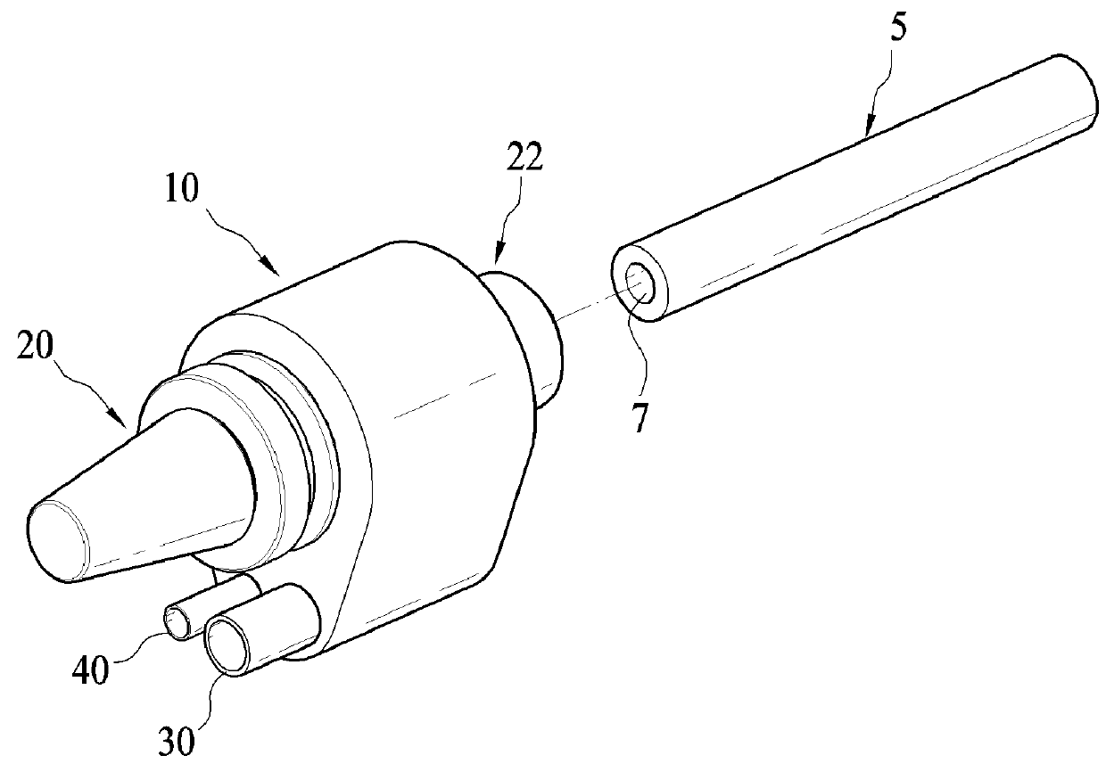
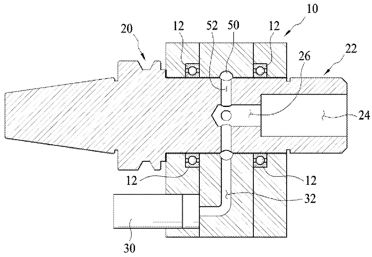
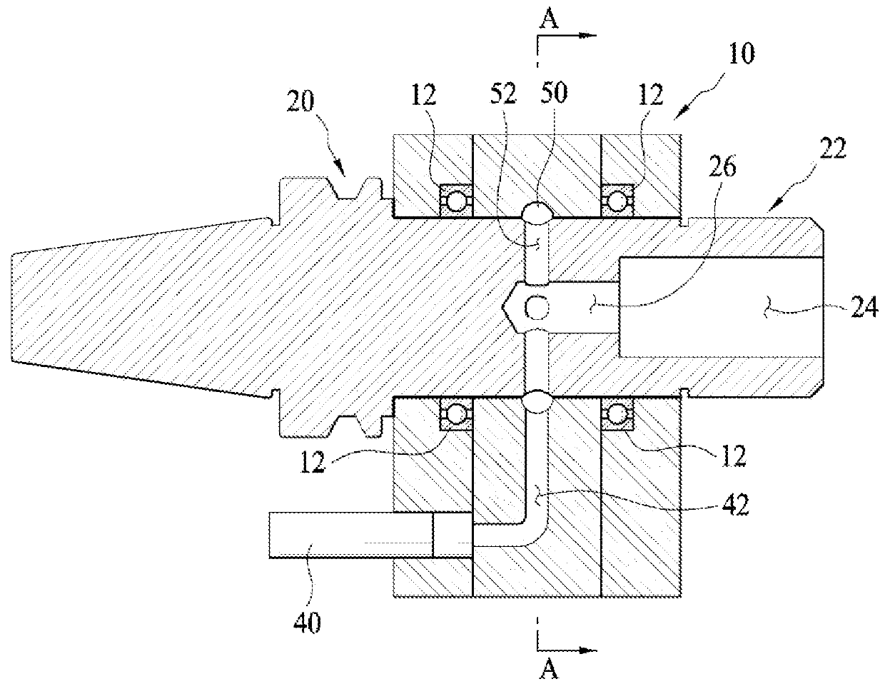
[0035]FIG. 1 is a perspective view illustrating a device for mixing and supplying fluids according to an embodiment of the present invention. Further, FIG. 2 is a sectional view illustrating a longitudinal cross section of the device for mixing and supplying fluids according to the embodiment of the present invention, and FIG. 3 is a sectional view illustrating another longitudinal cross section of the device for mixing and supplying fluids according to the embodiment of the present invention.

[0036]As illustrated in FIGS. 1 and 3, the device for mixing and supplying fluids according to the embodiment of t...


PUM


Abstract

A device for mixing and supplying fluids comprises: a fixing unit provided with a first flow path through which a first fluid flows, a second flow path through which a second fluid flows, and a through-hole; and a rotating unit, which is rotatably provided on the through-hole so as to penetrate the fixing unit, and which is provided at the front end with a fixing hole into which a processing tool is inserted and fixed, and a communication part which communicates with the first flow path and the fixing hole, so as to mix the first fluid and the second fluid and supply the mixture to the processing tool.

Description

TECHNICAL FIELD[0001]The present invention relates to a fluid supply device configured to spray fluid and, more particularly, to a device for mixing and supplying fluids, which mixes a first fluid and a second fluid with each other, and supplies the mixed fluid to a processing tool.BACKGROUND ART[0002]In general, in a process of processing an object such as metal, heat having high temperature is generated, and this heat causes dangers of deforming and damaging a workpiece and causes wear and deformation of tools configured to perform processing as well. Thus, when an object processing operation is performed to prevent the deformation, the damage and the wear, cryogenic fluid for cooling, such as liquid nitrogen, cutting oil for reducing friction or the wear of the tools, and the like are sprayed to an area to be processed.[0003]However, in the related art, a system for spraying the cryogenic fluid and the cutting oil is manufactured by separate devices. Thus, in the related art, the...

Claims


Application Information

Patent Timeline
Patent Type & Authority Applications(United States)
IPC IPC(8): B23Q11/10B23Q11/14
CPCB23Q11/1015B23Q11/14B23Q11/1046B23Q11/1053B23Q2220/008Y02P70/10B23Q11/10B23Q11/103
Inventor PARK, KYUNG HEELEE, DONG YOONLEE, SEOK WOOKIM, TAE-GON
Owner KOREA INST OF IND TECH
Why Eureka
Try Eureka