Method and Apparatus for Compliant Robotic End-Effector

a technology of robotic end-effectors and end-effectors, which is applied in the direction of programmable manipulators, joints, measurement gauges, etc., can solve the problems of variance in the target location of workpieces, inability to determine the constant workcell and workpiece conditions, and inability to achieve accurate end-effector alignment with workpiece features

Active Publication Date: 2018-04-19
THE BOEING CO
View PDF0 Cites 37 Cited by
  • Summary
  • Abstract
  • Description
  • Claims
  • Application Information

AI Technical Summary

Problems solved by technology

However, for some applications, especially those involving large parts, deterministic assumptions about constant workcell and workpiece conditions usually is not valid.
For example, changing environmental conditions, such as thermal expansion and/or contraction of a workpiece, often results in variances in the target locations on a workpiece.
For these robotics applications in which the target locations on a workpiece may vary, achieving accurate end-effector alignment with workpiece features is difficult.
In situations where an operation needs to precisely align the end-effector with a feature on the workpiece, such as inserting a tool into a hole for measurement types of tasks, incorrect placement of the end-effector may cause damage to the end-effecto

Method used


Image

  • Method and Apparatus for Compliant Robotic End-Effector
  • Method and Apparatus for Compliant Robotic End-Effector
  • Method and Apparatus for Compliant Robotic End-Effector

Examples


Embodiment Construction

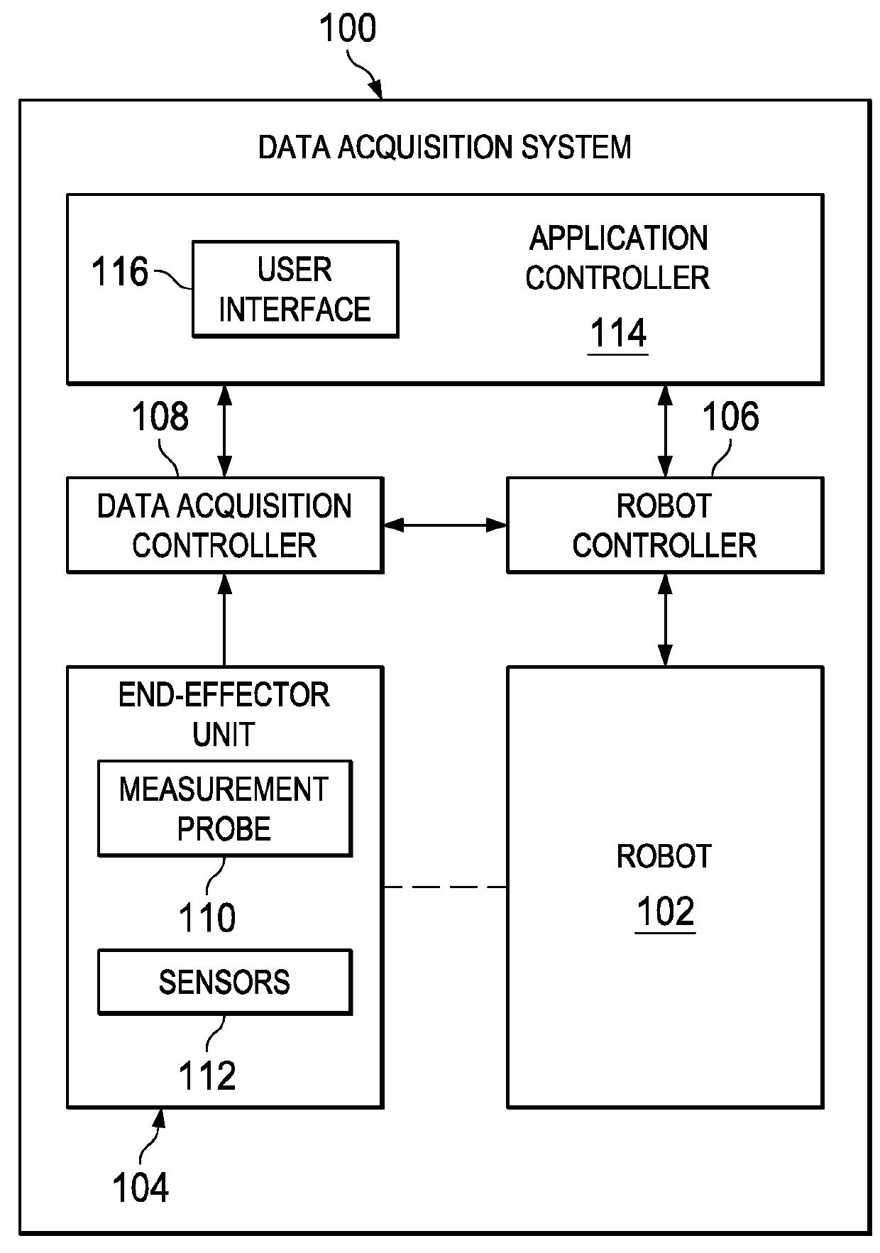
[0046]The illustrative embodiments take into account different considerations. For example, the illustrative embodiments take into account that it may be desirable to perform manufacturing applications involving a robot operator. Furthermore, the illustrative embodiments take into account that it may be desirable to have a method and apparatus for to precisely positioning the robot with respect to a workpiece, and perform manufacturing operations thereon. In particular, the illustrative embodiments take into account that it may be desirable to have a method and apparatus for precisely positioning the robot with respect to large workpieces, such as manufactured airplane components, and accurately measure hole or cutout thickness thereon.

[0047]Thus, the illustrative embodiments provide a method and apparatus that enables end-effector alignment with workpiece features in situations where potential discrepancies exist between nominal locations of workpieces and workpiece features and th...


PUM


Abstract

A method and apparatus for performing an operation on a workpiece using a multi-axis compliant end-effector for attachment to a robotic device. The end-effector is positioned at a nominal location of a workpiece feature on which the operation is to be performed. The end-effector is passively aligned with the workpiece feature by contacting the end-effector with the workpiece feature. The operation is performed on the workpiece feature in response to aligning the end effector with the workpiece feature.

Description

BACKGROUND INFORMATION1. Field[0001]The present disclosure relates generally to robotic manufacturing operations, and in particular, to positioning an end-effector attached to a robotic arm for manufacturing applications. Still more particularly, the present disclosure relates to a method and apparatus for accurately positioning a robotic end-effector on workpieces having variances in the target locations.2. Background[0002]In manufacturing applications involving control of robotic arm devices, it is necessary to precisely position the robot manipulator or end effector with respect to the workpiece on which any operations are to be performed. Many applications that use robotic arm devices assume a deterministic approach to position and orientation control for the robot. This deterministic approach expects the robotic workcell conditions to be constant and the motion control of the robot will always produce the same results for every new workpiece.[0003]However, for some applications...

Claims


Application Information

Patent Timeline
IPC IPC(8): B25J9/16
CPCB25J9/1692B25J9/1669B25J15/00B25J17/0208B25J17/0233B25J17/0275G01B5/06G01B3/28B25J9/1633B25J13/081G01B3/20
Inventor TROY, JAMES J.WRIGHT, DANIEL J.LEA, SCOTT W.
Owner THE BOEING CO
Why Eureka
Try Eureka