Method and device for monitoring an area ahead of a vehicle

a technology for monitoring an area and a vehicle, applied in the field of methods and devices, can solve problems such as the loss of objects from the detection area, and achieve the effect of rapid and efficient operation

Active Publication Date: 2018-04-19
ROBERT BOSCH GMBH
View PDF7 Cites 2 Cited by
  • Summary
  • Abstract
  • Description
  • Claims
  • Application Information

AI Technical Summary

Benefits of technology

[0018]The approach presented here furthermore provides a device which is designed to carry out, control, and / or implement the steps of a variant of a method provided here in corresponding units. The object on which the present invention is based may also be achieved rapidly and efficiently by this embodiment variant of the present invention in the form of a device.

Problems solved by technology

A sensor which is fixedly connected to the vehicle may lose an object from its detection area due to the pitching motion.

Method used


Image

  • Method and device for monitoring an area ahead of a vehicle
  • Method and device for monitoring an area ahead of a vehicle
  • Method and device for monitoring an area ahead of a vehicle

Examples


Embodiment Construction

[0025]In the description below of advantageous exemplary embodiments of the present invention, identical or similar reference numerals are used for the elements which are shown in the various figures and act similarly, a repeated description of these elements being omitted.

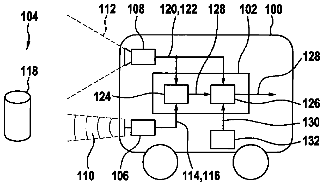
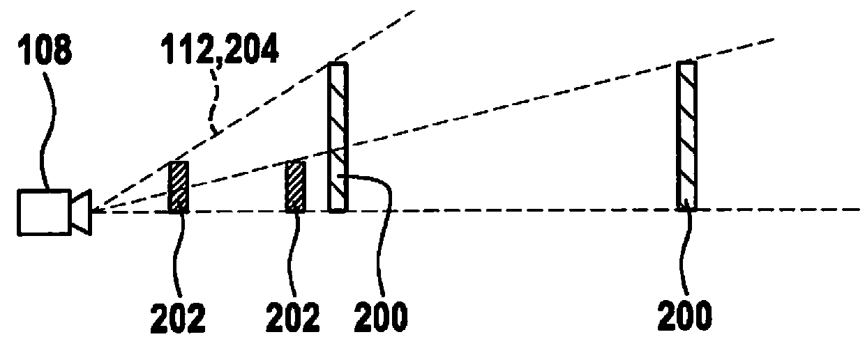
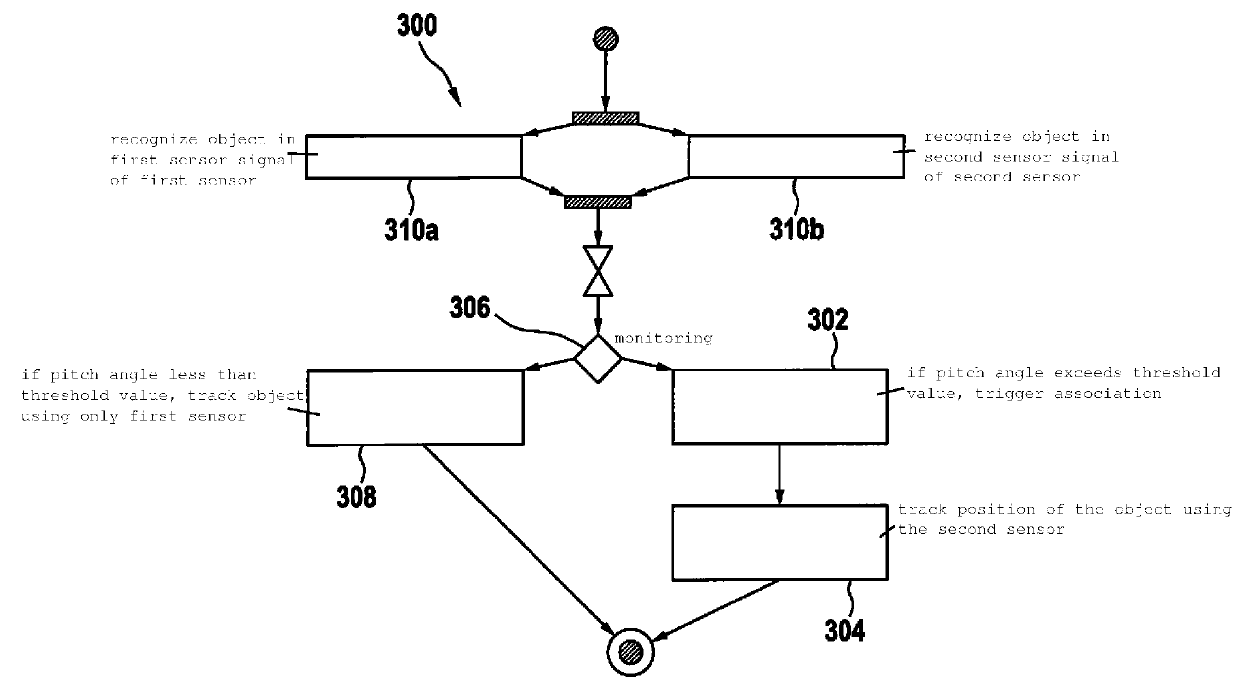
[0026]FIG. 1 shows an illustration of a vehicle 100 including a device 102 according to one exemplary embodiment. Device 102 is designed to monitor an area 104 ahead of vehicle 100. Device 102 is connected for this purpose to a first sensor 106 of vehicle 100 and a second sensor 108 of vehicle 100. Both sensors 106, 108 are oriented toward area 104. First sensor 106 has a first vertical detection angle 110. Second sensor 108 has a second vertical detection angle 112. Second detection angle 112 is greater than first detection angle 110. Second detection angle 112 completely covers first detection angle 110 from a certain distance here.

[0027]First sensor 106 provides a first sensor signal 114. At least one item of d...


PUM


Abstract

A method for monitoring an area ahead of a vehicle, the vehicle including a first sensor oriented in the direction of the area and a second sensor oriented in the direction of the area, the second sensor having a greater vertical detection angle than the first sensor, in a step of associating, an item of distance information detected by the first sensor is associated with an object detected by the second sensor in the area. In a step of tracking, a position of the object is tracked while using the second sensor when the object leaves the detection angle of the first sensor due to a pitch angle of the vehicle.

Description

FIELD[0001]The present invention is directed to a device or a method according to the definition of the species in the independent claims. The present invention is also directed to a computer program.BACKGROUND INFORMATION[0002]A vehicle may carry out a pitching motion during an acceleration process or a deceleration process. A sensor which is fixedly connected to the vehicle may lose an object from its detection area due to the pitching motion.[0003]Conventionally, triggering is frequently carried out using two items of sensor information. The signals which result in the triggering usually only come from a first sensor, however. Thus, for example, in the case of an emergency brake assistant, an object is recognized by the radar sensor and the relative velocity and / or the crash time is predicted. A second sensor (for example, a video sensor) is used to supply an object confirmation and enable the emergency braking. The signal which results in the triggering of the emergency brake as...

Claims


Application Information

Patent Timeline
Patent Type & Authority Applications(United States)
IPC IPC(8): B60W30/095G01S13/86G01S13/93G01S13/72G06K9/00G06T7/246G01S13/931
CPCB60W30/095G01S13/867G01S13/931G01S13/72G06K9/00805G06T7/246G01S2013/9375G01S2013/9353B60W2420/42B60W2420/52G06T2207/30261G01S2013/932G01S2013/93271G06V20/58
Inventor FOLTIN, JOHANNES LUDWIG
Owner ROBERT BOSCH GMBH
Why Eureka
Try Eureka