

Mounting Device for a Fitting Panel
a technology for mounting devices and fittings, which is applied in the direction of pipes, pipes/joints/fittings, domestic plumbing, etc., can solve the problems of predetermined height of fittings, irreversible damage to existing structures such as tiles, and the need for care and accuracy, etc., to achieve the effect of convenient and fast mounting, convenient installation and cost-effectiveness
- Summary
- Abstract
- Description
- Claims
- Application Information
AI Technical Summary
Benefits of technology
Problems solved by technology
Method used
Image

Examples
Embodiment Construction
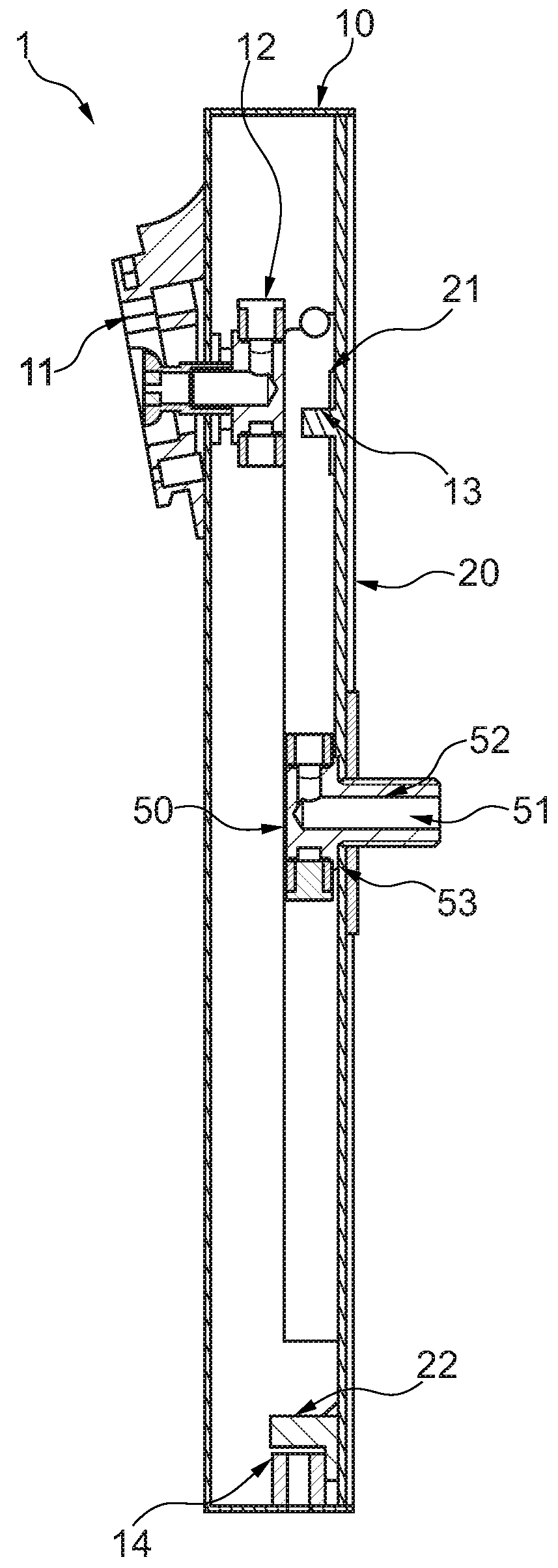
[0055]FIG. 1 shows a fitting unit 1, having a fitting panel 10 and a mounting device, wherein the mounting device includes a base element 20 and a fluid connection element 50. The base element 20 has a front side, pointing towards the fitting panel, and an opposing rear side. This rear side has a planar bearing surface, with which the base element may be provided on a wall or another surface that are not shown. On the fitting panel 10, a fitting is provided in a manner known per se, in the example shown a mounting fixture 11 for a shower head. A fitting connector 12 is also provided, via which water may be supplied to the shower head. Not shown, for reasons of clarity, but nevertheless easily understandable for a person skilled in the art, there is a connection between the fitting connector 12 and the fluid connection element 50. This may be provided for in a similarly known manner by flexible and, in particular, pressure-resistant hoses. The fluid connection element 50 of the mount...
PUM
 Abstract
Description
Claims
Application Information