
Electronic Control for Engine Block Heater Elements

a heater element and electronic control technology, applied in the field of engine block heaters, can solve the problems of wasting electricity, forgetting to plug the heater, adding unneeded costs, etc., and achieve the effect of accurately measuring the outside ambient air temperatur

Active Publication Date: 2018-04-19
BOSTIC MOTORS INC
View PDF4 Cites 2 Cited by
  • Summary
  • Abstract
  • Description
  • Claims
  • Application Information

AI Technical Summary

Benefits of technology

The electronic control and engine block heater described in this patent allow for various modes of operation. One mode is where the heater is connected to an electrical outlet but disconnected from the engine block heater element, another mode is where it is connected at a specific time based on a calculated temperature, a third mode is where it is regulated to maintain the engine ready temperature, and a fourth mode is where it is always connected. The engine block heater includes a controller with a printed circuit board and temperature sensor, and the controller is sealed in a housing to prevent water damage. The patent text also describes the specific features and benefits of the electronic control and engine block heater.

Problems solved by technology

As a result, a user either has to remember to plug in the engine block heater a certain time prior to starting and / or using the vehicle, or must keep the engine block heater plugged in and on at all times. This clearly can lead to forgetting to plug in the engine block heater in enough time prior to starting and / or using the vehicle, and / or having the engine block heater powered on for longer periods of time, thereby wasting electricity and adding unneeded costs.
This clearly can lead to forgetting to plug the engine block heater in and / or miscalculations in the amount of time required for the engine block heater to heat the engine prior to starting and / or using the vehicle.

Method used


Image

  • Electronic Control for Engine Block Heater Elements
  • Electronic Control for Engine Block Heater Elements
  • Electronic Control for Engine Block Heater Elements

Examples


Embodiment Construction

[0063]In describing the exemplary embodiments of the present disclosure, as illustrated in FIGS. 1-17, specific terminology is employed for the sake of clarity. The present disclosure, however, is not intended to be limited to the specific terminology so selected, and it is to be understood that each specific element includes all technical equivalents that operate in a similar manner to accomplish similar functions. Embodiments of the claims may, however, be embodied in many different forms and should not be construed to be limited to the embodiments set forth herein. The examples set forth herein are non-limiting examples, and are merely examples among other possible examples.

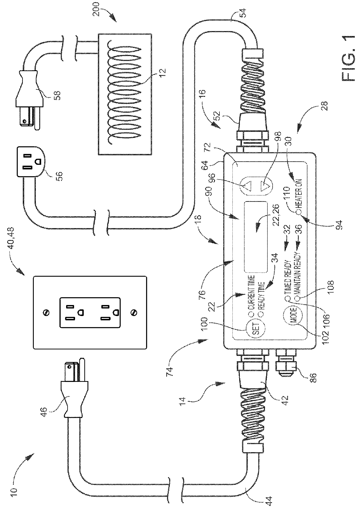
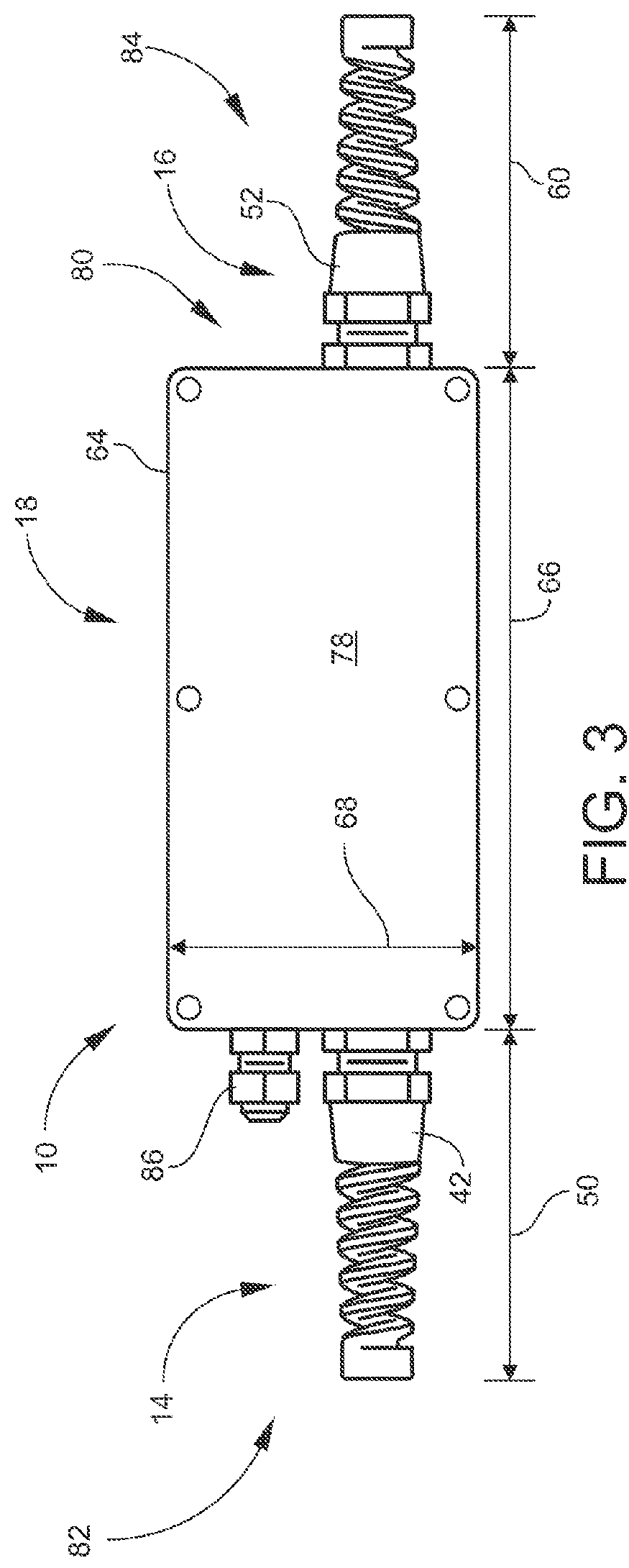
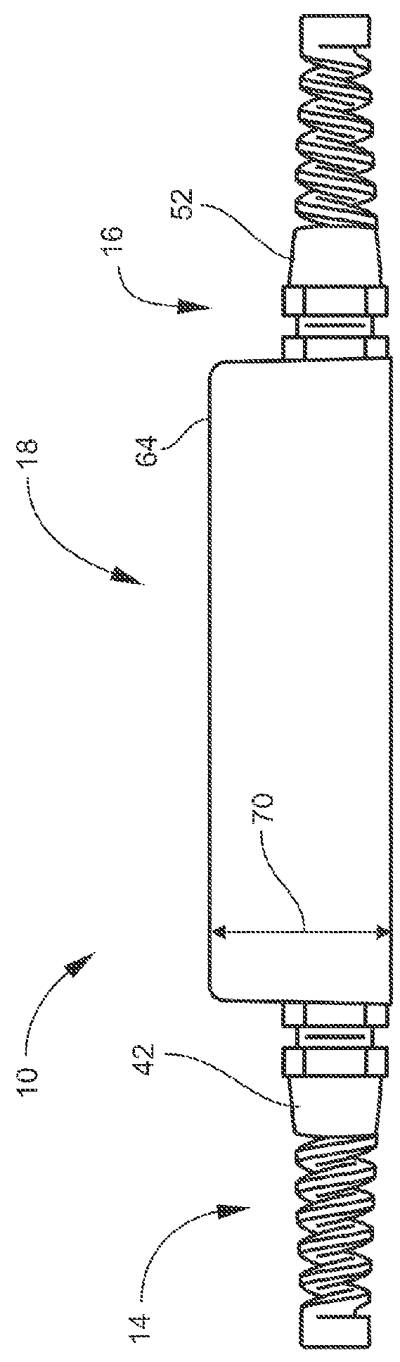
[0064]Referring now to FIGS. 1-7 by way of example, and not limitation, therein is illustrated example embodiments of electronic control 10 for engine block heater element 12 of engine block heater 200. Electronic control 10 may be for providing a control to engine block heater 200 that can turn the engine blo...


PUM


Abstract

An electronic control for engine block heater elements for heating an engine to an engine ready temperature includes a power input, a power output, and a controller. The controller includes a clock for keeping a time and a temperature sensor for sensing a temperature. The controller is configured for controlling the power from the power input to the power output in at least two modes of operation for heating the engine to the engine ready temperature. The second mode of timed ready is where the power from the power input to the power output is connected at a pre-calculated time interval for the purpose of making ready the subject vehicle for starting at the desired start time as set by the user. The third mode of maintain ready is where the power from the electrical outlet to the engine block heater element is regulated to maintain the engine ready temperature.

Description

CROSS-REFERENCE TO RELATED APPLICATIONS[0001]NoneFEDERALLY SPONSORED RESEARCH OR DEVELOPMENT[0002]NonePARTIES TO A JOINT RESEARCH AGREEMENT[0003]NoneREFERENCE TO A SEQUENCE LISTING[0004]NoneBACKGROUND OF THE DISCLOSURETechnical Field of the Disclosure[0005]The instant disclosure generally relates to engine block heaters. More particularly, the instant disclosure relates to an electronic control for engine block heater elements.Description of the Related Art[0006]An engine block heater warms an engine to increase the chances that the engine will start as well as warm up the vehicle faster than it normally would in extremely cold weather. The most common type of engine block heater is an electric heating element in the cylinder block, connected through a power cord often routed through the vehicle's grille. In some embodiments, the engine block heater may replace one of the engine's core plugs. In this fashion, the heater element is immersed in the engine's coolant, which then keeps m...

Claims


Application Information

Patent Timeline
Patent Type & Authority Applications(United States)
IPC IPC(8): F02N19/02B60L1/08
CPCF02N19/02F02N2200/023B60L2240/425B60L1/08F02N11/0811F02N19/04
Inventor AIELLO, JEFFREY GRAHAM
Owner BOSTIC MOTORS INC
Learn More