Vapor chamber and heat pipe combined structure and combining method thereof

a combined structure and heat pipe technology, applied in the direction of electrical apparatus construction details, basic electric elements, lighting and heating apparatus, etc., can solve the problems of high manufacturing cost, complicated manufacturing process, and limited heat conductivity of working fluid, so as to improve the reflux speed of working fluid and improve the thermal conduction performance

Active Publication Date: 2018-04-19
TAIWAN MICROLOOPS CORP
View PDF2 Cites 20 Cited by
  • Summary
  • Abstract
  • Description
  • Claims
  • Application Information

AI Technical Summary

Benefits of technology

[0008]This disclosure has the following effects. The first capillary tissue and the second capillary tissue are attached to each other to improve the reflux speed of the working fluid. The fixing section of a different structure is attached closely to the corresponsive attaching portion of the upper metal casing, not just attaching the first capillary tissue to the second capillary tissue easily only, but also returning the liquid-sta

Problems solved by technology

Although a gas-state working fluid in the heat pipe flows in the same direction, the heat conducted by the working fluid is very limited due to the limitation of its volume.
On the other hand, the vapor chamber has a relatively large heated surface for attaching a heat source and conducting heat directly, but the flowing direction of the gas-state working fluid is disordered, and the heat conduction and dissipation performance of the vapor chamber is limited.
Although the conventional vapor chamber an

Method used


Image

  • Vapor chamber and heat pipe combined structure and combining method thereof
  • Vapor chamber and heat pipe combined structure and combining method thereof
  • Vapor chamber and heat pipe combined structure and combining method thereof

Examples


Embodiment Construction

[0018]The technical contents of this disclosure will become apparent with the detailed description of preferred embodiments accompanied with the illustration of related drawings as follows. It is intended that the embodiments and figures disclosed herein are to be considered illustrative rather than restrictive.

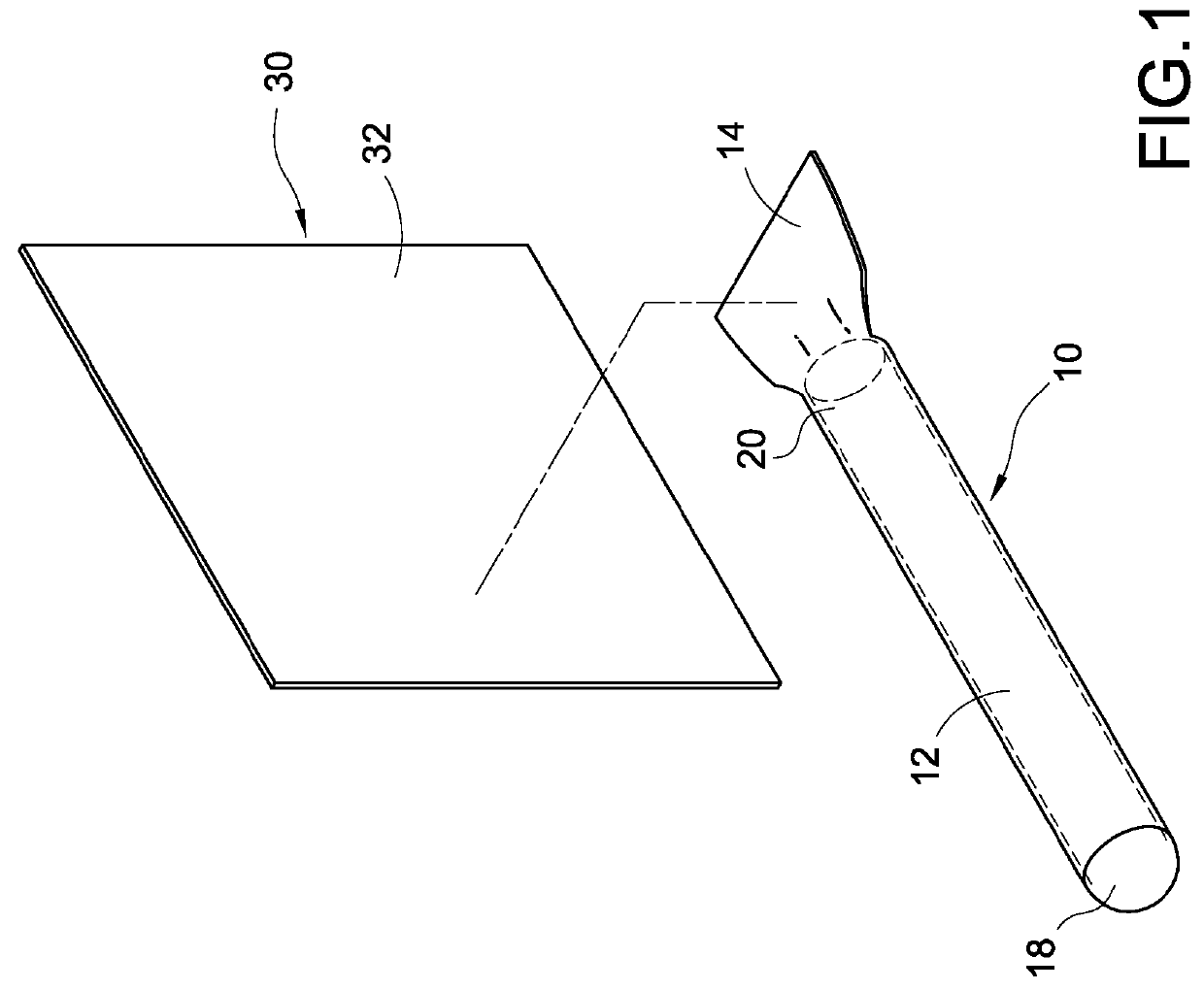
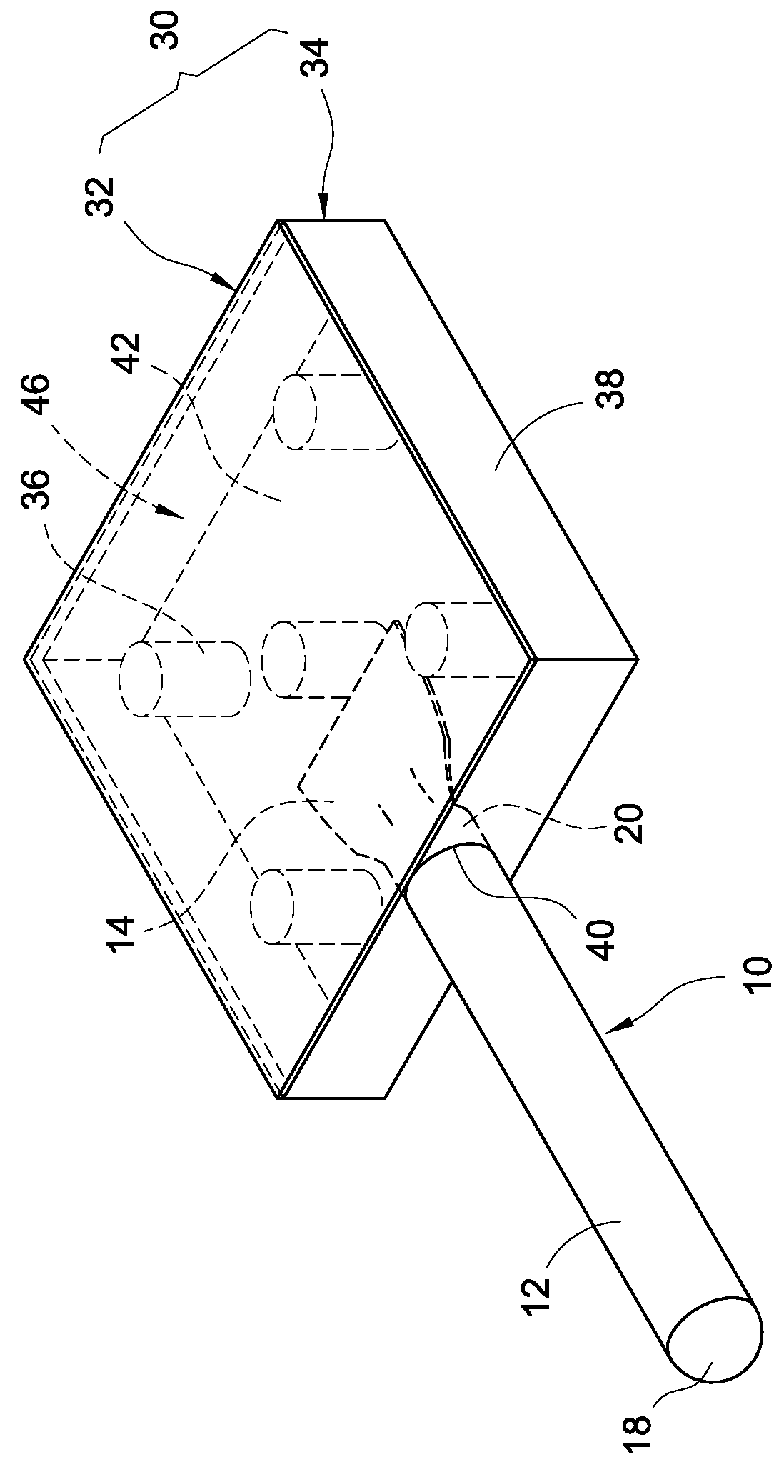
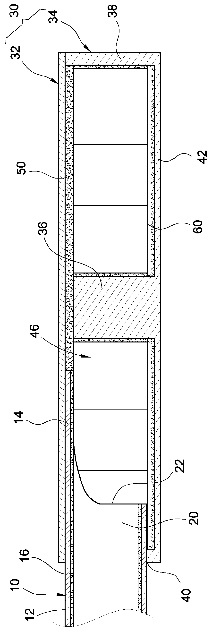
[0019]With reference to FIGS. 1 to 3 for a vapor chamber and heat pipe combined structure of this disclosure, the vapor chamber and heat pipe combined structure comprises a heat pipe 10, a vapor chamber 30 and a working fluid 60. The vapor chamber and heat pipe combined structure can be applied to the heat dissipation for computer hosts, servers, or industrial host systems, etc.

[0020]The heat pipe 10 comprises a pipe body 12, a fixing section 14 extended from an end of the pipe body 12, and a first capillary tissue 16 installed in the pipe body 12 and along the fixing section 14. The pipe body 10 is made of a material such as copper, aluminum, or other appropriate alloys with...


PUM


Abstract

A vapor chamber and heat pipe combined structure and method; the vapor chamber and heat pipe combined structure includes a heat pipe, a vapor chamber and a working fluid. The heat pipe includes a pipe body, a fixing section, and a first capillary tissue. The vapor chamber includes an upper metal casing, a lower metal casing, a containing chamber and a second capillary tissue installed in the containing chamber. The working fluid is filled into the containing chamber, and the fixing section of the heat pipe is coupled to the upper metal casing, so that the first capillary tissue is coupled to the second capillary tissue. The combined structure facilitates the connection and fixation of the heat pipe and improves the reflux speed of the liquid-state working fluid.

Description

FIELD OF THE INVENTION[0001]The technical field generally relates to a thermal conduction technology, more particularly, to a vapor chamber and heat pipe combined structure and a combining method thereof.BACKGROUND OF THE INVENTION[0002]As the computing speed of electronic devices increases, the heat generated by the electronic devices becomes increasingly higher. To overcome the issue of generating a large quantity of heat, manufacturers have introduced and used a heat pipe and a vapor chamber with good thermal conductivity for dissipating heat. Although a gas-state working fluid in the heat pipe flows in the same direction, the heat conducted by the working fluid is very limited due to the limitation of its volume. On the other hand, the vapor chamber has a relatively large heated surface for attaching a heat source and conducting heat directly, but the flowing direction of the gas-state working fluid is disordered, and the heat conduction and dissipation performance of the vapor ...

Claims


Application Information

Patent Timeline
IPC IPC(8): F28D15/02F28D15/04F28F9/26
CPCF28D15/0275F28D15/04F28F2275/06F28F9/26F28F2255/18F28D15/0266H01L23/427H05K7/20336
Inventor LIN, CHUN-HUNG
Owner TAIWAN MICROLOOPS CORP
Why Eureka
Try Eureka