Actuator

a technology of actuators and actuators, applied in the field of actuators, can solve the problems of ever increasing requirements, and achieve the effects of adjusting the transmission capacity, increasing the opening force, and prolonging the rotational trajectory

Inactive Publication Date: 2018-04-26
HANON SYST
View PDF6 Cites 4 Cited by
  • Summary
  • Abstract
  • Description
  • Claims
  • Application Information

AI Technical Summary

Benefits of technology

[0009]This makes it possible to specifically adjust the transmission capacity depending on the respective threading segment, in the sense that the transmission capacity in the first and second threading segment is greater, while in the third threading segment lying in between them it is smaller. This allows for the exploitation of the flexibility in terms of capacity and trajectory. In this manner, the translational movement of the drive element can be advantageously utilized for a valve.
[0010]This allow for achieving at least one of the following advantages:
[0011]Due to the more moderate increase in the first and second threading segment, a greater opening force can be transmitted, which correlates with a longer rotational trajectory. As a result, a comparatively stronger force may be used, for instance at the beginning of the opening or closing movement of the valve, in order to perform the movement. Due to the fact that the pitch angle in the first and second threading segment is smaller than the increase in the third threading segment, a smaller electric motor can be used as a power source, since the higher application of force can be obtained over the moderate increase. The result is, for instance, that a smaller electrical drive can be built in.
[0012]A further point is that when a lower drive performance should suffice, this drive is also less energy-intensive, which leads to an overall lower energy consumption. This is particularly noticeable, because force must continuously, that is: constantly, be exerted in an opening position as well as in a closing position of the valve. A higher actuation force may therefore be achieved in both end positions of the valve at a low energy supply.
[0013]Furthermore, the higher increase in the third threading segment allows for faster adjustments of a valve in the interim section. This increases the response time, or respectively, the changeover time within the valve can be switched.
[0014]An additional point is that when using the valve, it is important in practice that the valve is not unintentionally switched by other forces. Specifically, a gas exerts gas forces. Due to the fact that the increase in the first and second threading segment is higher, it is possible to generate a correspondingly high counterforce in these sections, which makes it less likely for gas forces to change the position of the valve.

Problems solved by technology

However, they are faced with ever increasing requirements.

Method used


Image

  • Actuator
  • Actuator
  • Actuator

Examples


Embodiment Construction

[0021]An embodiment of the present invention is described below in detail with reference to the figures.

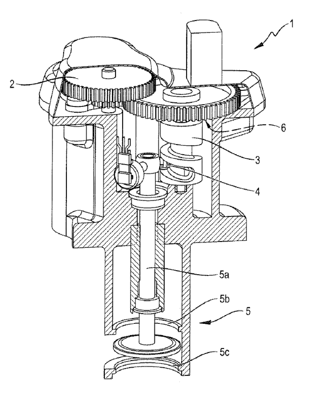
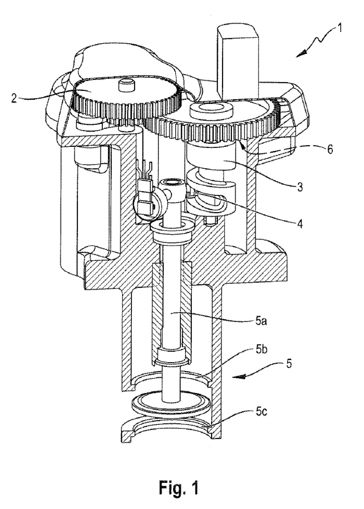
[0022]FIG. 1 shows the actuator 1 with a drive 2, which features two cogwheels. The drive 2 of the actuator 1 shown is a rotary drive. The rotational threaded element 3 might be a screw with threading or with partial threading. The screw is one of the type also called “worm”. The threaded element 3 is engaged by the translationally driven drive element 4 in such a manner that a rotation of the threaded element 3 leads to a translational movement of the drive element 4. The drive element 4 may, for instance, be a segment protruding from the valve tappet 5a, a wheel, a roll, or another element. The rotational movement of the rotational drive is therefore converted into a lifting movement of the valve tappet 5a. The valve element 5 is connected with the actuator 1 or with the drive element 4, respectively, by means of the valve tappet 5a.

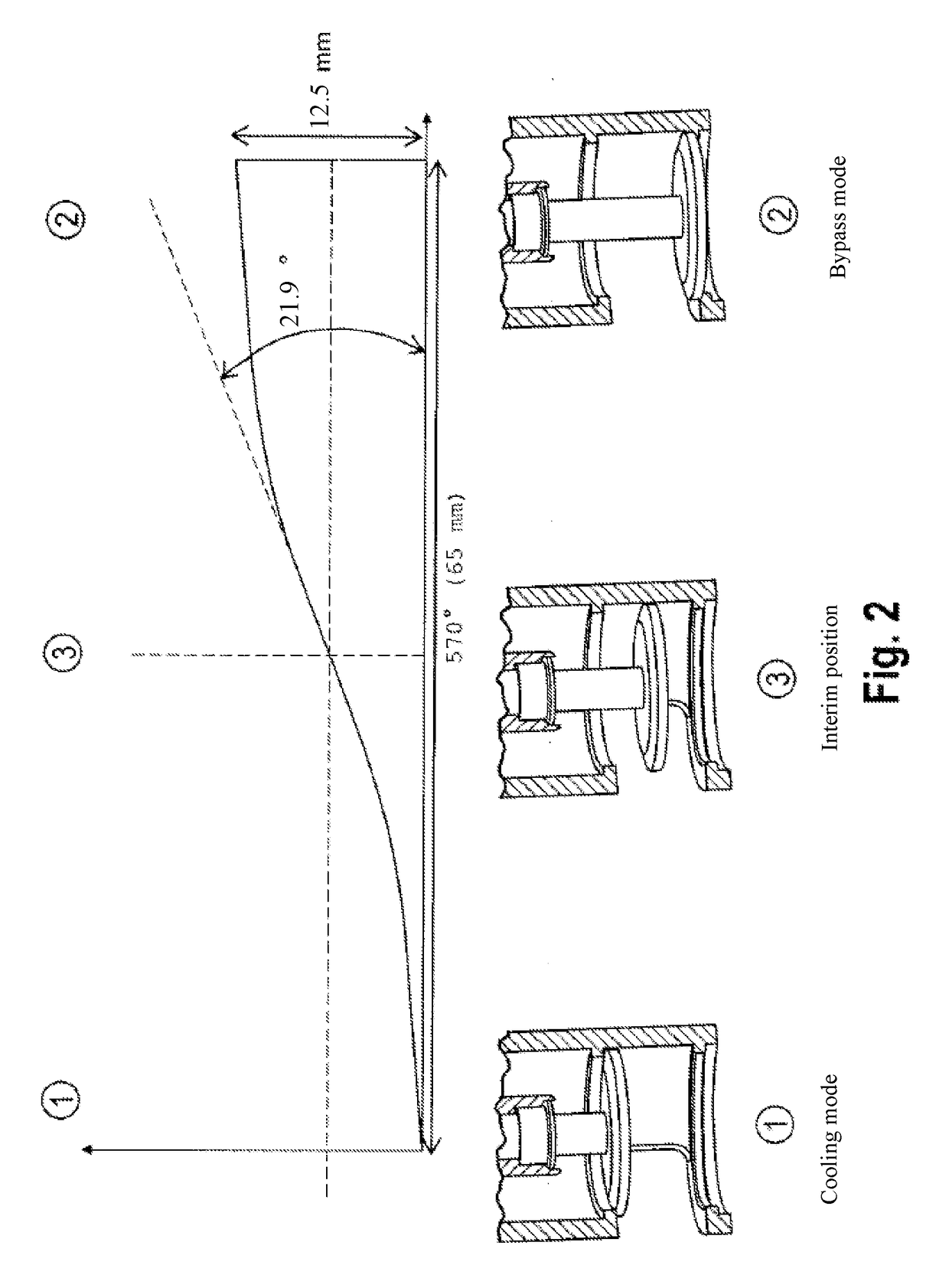
[0023]FIG. 2 shows the pitch angle of the thr...


PUM


Abstract

The invention pertains to an actuator for actuating a valve, the valve featuring a drive and at least one rotational threaded element with a first and a second threading segment and a third threading segment positioned between them. The actuator further features a drive element that is translationally driven by the threaded element. The actuator according to the invention is characterized in that the pitch angle in the third threading segment is greater than the pitch angle in the first and second threading segment.

Description

CROSS REFERENCE TO RELATED PATENT APPLICATION[0001]This patent application claims priority to German Patent Application No. 10 2016 220 780.6 filed Oct. 21, 2016, the entire disclosure of which is hereby incorporated herein by reference.FIELD OF THE INVENTION[0002]The invention pertains to an actuator and a combination of an actuator with a valve element, as well as an exhaust gas recirculation valve, a waste gate, and variable turbine geometry of an exhaust gas turbo charger.BACKGROUND OF THE INVENTION[0003]Devices of the aforementioned type are commonly used in combustion engines where, depending on their operating status, exhaust gas must be supplied to the fresh air side in order to reduce fuel consumption and pollutant emissions. A translationally movable valve tappet can be actuated by means of the actuator over a corresponding valve.[0004]It is known from EP 2 418 373 A1 that the rotational threaded element over which the valve is translationally moved features at least two s...

Claims


Application Information

Patent Timeline
Patent Type & Authority Applications(United States)
IPC IPC(8): F02B37/18F16K31/04
CPCF02B37/186F16K31/047F02M26/54F02M26/66F16K31/528Y02T10/12F02M26/52F16K1/34F16K31/53
Inventor LEHNERT, ROMANSCHIEKER, MANUELTHIERY, CHRISTOPH
Owner HANON SYST
Why Eureka
Try Eureka