Combustion device and combustion device system including combustion device

a combustion device and combustion device technology, applied in the direction of combustion treatment, fluid heaters, lighting and heating apparatus, etc., can solve the problems that the exhaust fans of the other combustion devices cannot be activated, and the existence of the combustion device which is performing the combustion operation cannot be detected by the other combustion devices, so as to inhibit the combustion

Active Publication Date: 2018-04-26
NORITZ CORP
View PDF1 Cites 2 Cited by
  • Summary
  • Abstract
  • Description
  • Claims
  • Application Information

AI Technical Summary

Benefits of technology

[0009]In accordance with this configuration, in a case where a condition in which the information set by the setting section indicates the common vent discharge state and a condition in which the combustion control section cannot communicate with the linkage control section or at least one of the other combustion control sections are met, the combustion control section of each of the plurality of combustion devices inhibits the combustion in the combustion device to which this combustion control section belongs (combustion in the combustion device corresponding to this combustion control section). This makes it possible to reliably prevent a situation in which while one of the plurality of combustion devices is performing the combustion operation in the common vent discharge state, the operation commands for the exhaust fans of the other combustion devices do not reach the combustion devices and thereby back flow of the exhaust gas occurs. Therefore, it becomes possible to properly perform a combustion inhibiting operation of each of the plurality of combustion devices if a communication abnormality (failure) between the plurality of combustion devices occurs in a case where the common exhaust passage is used for the plurality of combustion devices.
[0010]The linkage control section may include an information obtaining section which obtains the information set by the setting section from at least one of the plurality of combustion devices; and a second memory section which stores therein connection configurations between the linkage control section and the plurality of combustion control sections, wherein the linkage control section may determine whether or not the linkage control section can communicate with each of the plurality of combustion control sections of the plurality of combustion devices, and send to the combustion control sections being in communication with the linkage control section, combustion inhibiting commands directing inhibition of combustion in the combustion devices corresponding to the combustion control sections being in communication with the linkage control section, in a case where the linkage control section determines that the linkage control section cannot communicate with at least one of the plurality of combustion control sections and the information obtained from the setting section indicates the common vent discharge state, and wherein the combustion control sections being in communication with the linkage control section may inhibit the combustion in the combustion devices to which the combustion control sections belong, in response to the combustion inhibiting commands received from...

Problems solved by technology

However, if a communication abnormality (failure) between the plurality of combustion devices occurs, the existence of the combustion device which is performing the combustion operation cannot be detected by the other comb...

Method used


Image

  • Combustion device and combustion device system including combustion device
  • Combustion device and combustion device system including combustion device
  • Combustion device and combustion device system including combustion device

Examples


embodiment 1

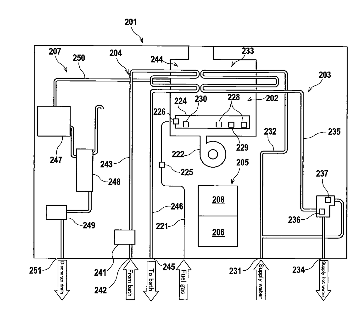
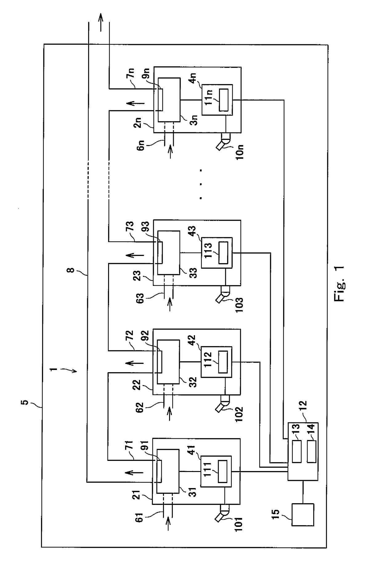
[0022]FIG. 1 is a block diagram showing the schematic configuration of a combustion device system including a plurality of combustion devices according to Embodiment 1 of the present invention. Referring now to FIG. 1, a combustion device system 1 of the present embodiment includes a plurality of (n) combustion devices 2i (i=1, 2, 3, . . . , n: n 2). Each of the plurality of combustion devices 2i includes a combustion section 3i and a combustion control section 4i which controls combustion in the combustion section 3i. The combustion control section 4i is constituted by, for example, a microcontroller. The plurality of combustion devices 2i are installed in an indoor environment 5.

[0023]Each of the plurality of combustion devices 2i includes an intake port 6i through which air is taken into the combustion section 3i in the indoor environment 5 and an exhaust port 7i through which an exhaust gas generated by combustion in the combustion section 3i is discharged in the indoor environm...

embodiment 2

[0037]Next, Embodiment 2 of the present invention will be described. FIG. 3 is a block diagram showing the schematic configuration of a combustion device system including a plurality of combustion devices according to Embodiment 2 of the present invention. In FIG. 3, the same constituents as those of FIG. 1 or the corresponding constituents are designated by the same reference symbols and will not be described repeatedly.

[0038]A combustion device system 1B of Embodiment 2 is different from the combustion device system 1 of Embodiment 1 in that a combustion control section (a first combustion control section) 41B which is one of a plurality of combustion control sections 41B, 42B of a plurality of combustion devices 21B, 22B functions as the linkage control section 12, and the plurality of combustion control sections 41B, 42B are communicatively coupled to each other via a communication line 16.

[0039]In the present embodiment, each of the two combustion control sections 41B, 42B of t...


PUM


Abstract

A combustion device includes a combustion control section which controls combustion in the combustion device; a setting section operated to set information indicating whether or not a plurality of combustion devices are in a common vent discharge state; and a memory section which stores therein connection configurations with the other combustion control sections to which the combustion control section is communicatively connected, and the combustion control section determines whether or not the combustion control section can communicate with a linkage control section or the other combustion control sections, and inhibits combustion in the combustion device to which the combustion control section belongs, in a case where the combustion control section determines that the combustion control section cannot communicate with the linkage control section or at least one of the other combustion control sections and the common vent discharge state is set by the setting section.

Description

CROSS-REFERENCE TO RELATED APPLICATION[0001]This application claims priority to and the benefit of Japanese Patent Application No. 2016-208833 filed on Oct. 25, 2016, the entire disclosure of which is incorporated herein by reference.1. FIELD OF THE INVENTION[0002]The present invention relates to a combustion device and a combustion device system including the combustion device.2. DESCRIPTION OF THE RELATED ART[0003]Regarding a combustion device system in which a plurality of combustion devices such as combustion / heating type hot water supply devices are connected to each other, a common vent system is known, in which a common exhaust passage is used for the plurality of combustion devices. For example, Japanese Laid-Open Patent Application Publication No. 2016-121851 and Japanese Patent No. 5852458 disclose such a common vent system. In this common vent system, air-intake is performed in an indoor area, and an exhaust gas is discharged to an outdoor area through a common duct (comm...

Claims


Application Information

Patent Timeline
IPC IPC(8): F24H9/20F23C6/02F23N5/26
CPCF24H9/2042F24H1/0027F23N5/265F23C6/02F23J11/12F23J2211/20F24H1/46F23N2231/28F23N2241/04F23N2237/02F24D2200/043F24H15/116F24H15/464F24H15/421F24H15/345F24H15/365
Inventor OKAMOTO, SHINICHIMUKO, TAKAO
Owner NORITZ CORP
Why Eureka
Try Eureka