Liquid Crystal Display Device With Peripheral Electrode

Active Publication Date: 2018-04-26
OMNIVISION TECH INC
View PDF2 Cites 0 Cited by
  • Summary
  • Abstract
  • Description
  • Claims
  • Application Information

AI Technical Summary

Benefits of technology

The invention provides a better way to distribute voltage changes across a transparent electrode of a display. This helps to make the display brighter and more uniform. Overall, the invention makes it possible to improve the performance of the display device.

Problems solved by technology

Moreover, in three-color systems, such variations in the intensities of individual colors can create perceived color distortions in the displayed image.
For these reasons, non-uniformity in the representation of intensity values across the display area is undesirable.

Method used


Image

  • Liquid Crystal Display Device With Peripheral Electrode
  • Liquid Crystal Display Device With Peripheral Electrode
  • Liquid Crystal Display Device With Peripheral Electrode

Examples


Embodiment Construction

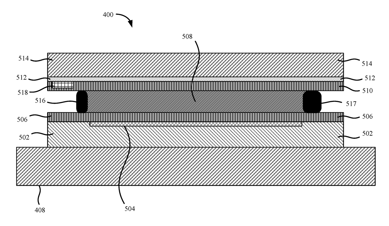
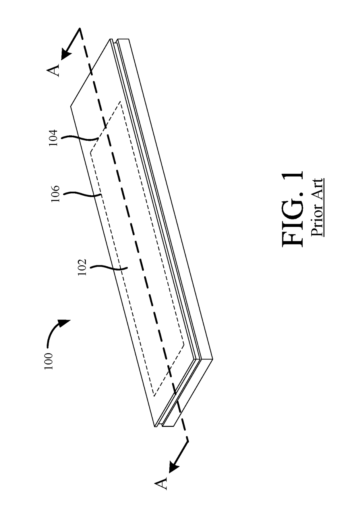
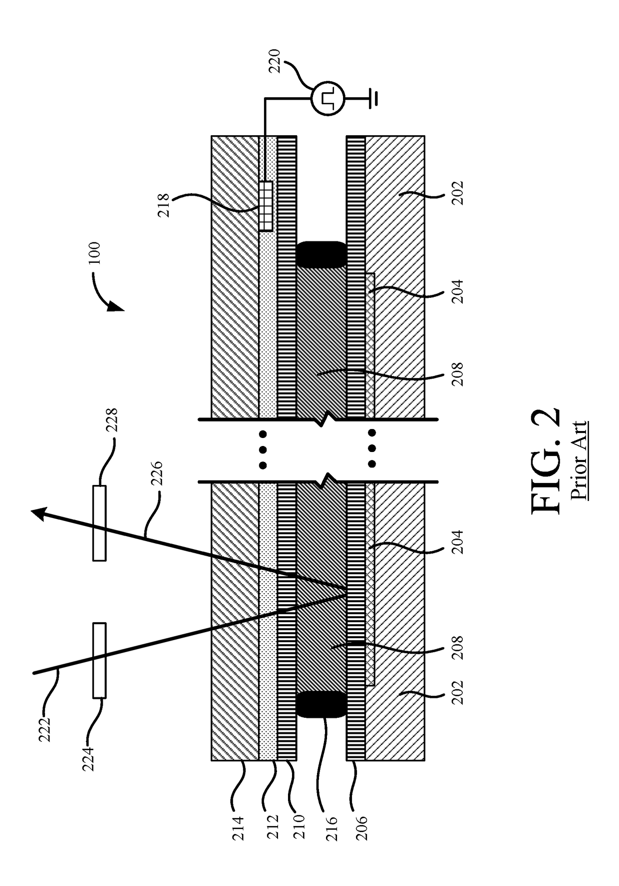
[0030]The present invention overcomes the problems associated with the prior art, by providing an input electrode that extends along and that is electrically-coupled along at least a portion of the periphery of the transparent electrode of an LCoS display device. The input electrode facilitates driving the transparent electrode with a high-frequency voltage waveform while minimizing intensity variation across the device's display area. In the following description, numerous specific details are set forth (e.g., particular input electrode designs, particular display device structures, etc.) in order to provide a thorough understanding of the invention. Those skilled in the art will recognize, however, that the invention may be practiced apart from these specific details. In other instances, details of well-known liquid crystal display manufacturing practices (e.g., pixel array formation, layer formation, etc.) and components have been omitted, so as not to unnecessarily obscure the p...


PUM


Abstract

A liquid crystal display device includes a first substrate, a pixel array formed on the first substrate, a transparent substrate, a liquid crystal layer disposed between the pixel array and the transparent substrate, a transparent electrode disposed between the transparent substrate and the liquid crystal layer, and an input electrode. The transparent electrode has a longer first edge and an orthogonal shorter second edge. The input electrode extends along, and is electrically coupled along, the first edge of the transparent electrode and has lower impedance than a portion of the transparent electrode overlying the pixel array. The input electrode can include additional portion(s) that extend along, and that are electrically-coupled along, the other edges of the transparent electrode. The input electrode reduces the common voltage propagation delay across the transparent electrode and improves reduces intensity variation over the display area, even for high-frequency common voltage waveforms.

Description

BACKGROUND OF THE INVENTIONField of the Invention[0001]This invention relates generally to liquid crystal displays, and more particularly to liquid crystal on silicon (LCoS) displays.Description of the Background Art[0002]Currently there is a demand for miniature display devices in various commercial and consumer applications. For example, LCoS display devices are being incorporated into many different mobile and automotive devices.[0003]FIG. 1 is a perspective view showing a known liquid crystal display device 100, which is a reflective LCoS light valve. Display device 100 is driven by image processing and control circuitry (not shown) to display images on a display area 102 thereof in accordance with image data received by display device 100. Display area 102 has a long, rectangular format and includes short sides 104 and long sides 106.[0004]FIG. 2 is a cross-sectional view of display device 100 taken along line A-A of FIG. 1. FIG. 2 shows that display device 100 is formed on a s...

Claims


Application Information

Patent Timeline
IPC IPC(8): G02F1/1343
CPCG02F1/13439G02F1/134309G02F1/1345G02F1/136277G06F2203/04113
Inventor FAN, CHUN-SHENG
Owner OMNIVISION TECH INC
Why Eureka
Try Eureka