
Root implant

a root implant and implant technology, applied in the field of root implants, can solve the problems of ineffective combination between dental implants and alveolar bones, inability to prevent loosening, and slippery surfaces of holes, so as to increase the positioning effect of root implants and prevent loosening problems

Inactive Publication Date: 2018-05-03
TAIWAN SHAN YIN INT CO LTD
View PDF6 Cites 0 Cited by
  • Summary
  • Abstract
  • Description
  • Claims
  • Application Information

AI Technical Summary

Benefits of technology

The invention is a root implant that prevents loosening and improves stability. It has a body with multiple openings and a joint section, allowing for the growth of accretions that securely attach to the implant. The implant also has a thread portion with fine and coarse threads, which helps distribute the accretions evenly and increases the stability of the implant. Overall, this root implant design ensures a secure and stable connection to the alveolar bone.

Problems solved by technology

Although the accretions can integrate with the dental implant, in view of a slippery surface of the dental implant, the slight displacements caused by an external force may result in the loosening problem of the accretions while the alveolar bone is recovered gradually.
Although the improved dental implant is processed by the multi-melting sintering method to form several holes to accommodate the accretions, an outer diameter and a depth of each hole are hardly to keep identical during the multi-melting sintering process.
Further, the multi-melting sintering method causes the surfaces of the holes to become slippery.
Thus, the holes are unable to accommodate the accretions successfully to result in an ineffective combination between the dental implant and the alveolar bone.
Hence, the accretions are unable to form toward a regular direction effectively when the accretions clamber between any two of the holes.
Furthermore, the sintered pellets may even result in the possibility of remaining the corrosive acid.

Method used


Image

  • Root implant
  • Root implant
  • Root implant

Examples


Embodiment Construction

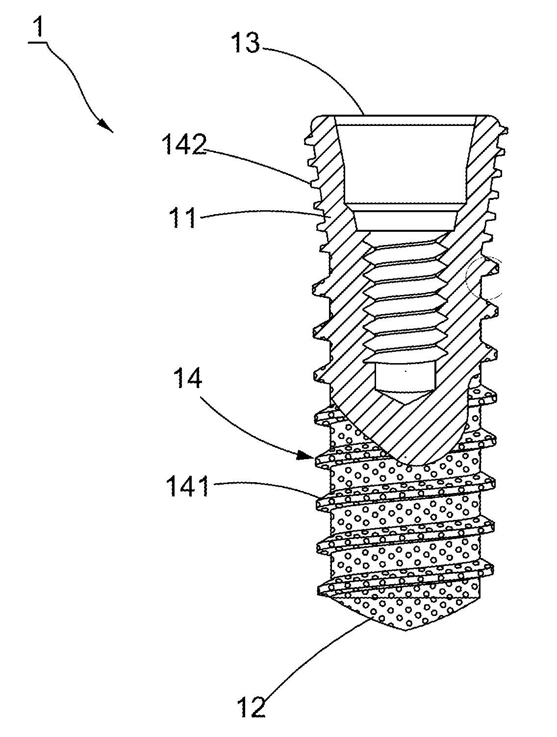
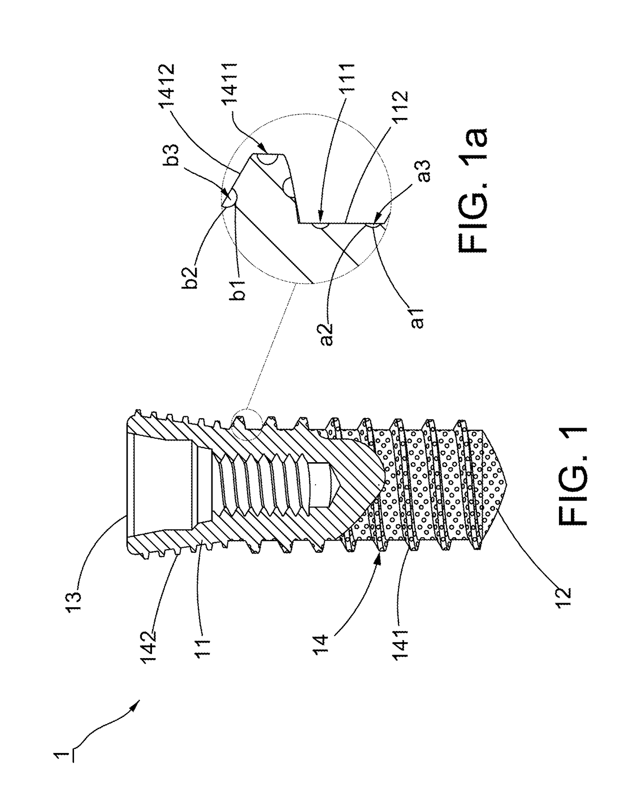
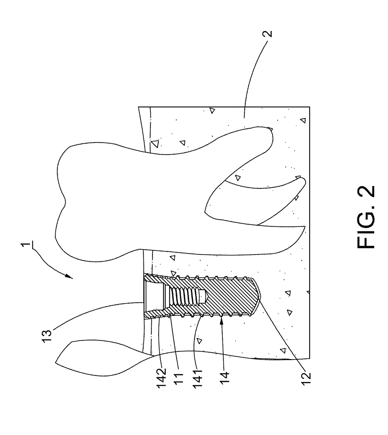
[0025]Referring to FIG. 1, a first preferred embodiment of a root implant 1 of this invention includes a body portion 11, a drilling portion 12 fitted on a first side of the body portion 11, a positioning hole 13 formed on a second side of the body portion 11 and opposed to the drilling portion 12, and a thread portion 14 fitted on the body portion 11 spirally. Referring to FIG. 1a, the body portion 11 has a plurality of first openings 111 formed thereon. Any two of the first openings 111 define a first joint section 112. Each first opening 111 is further divided into a first bottom wall a1, a first surrounding wall a2 connected with the first bottom wall a1, and a first accommodation room a3 defined by each first bottom wall a1 and each first surrounding wall a2. Each first accommodation room a3 communicates with the outside. Meanwhile, the first openings 111 are processed by a high-energy optothermal method to form the first openings 111 with precise dimensions and equidistant arr...


PUM


Abstract

A root implant includes a body portion, a drilling portion formed on the body portion, a positioning hole formed opposite to the drilling portion, and a thread portion spiraled on the body portion. The body portion and the coarse thread have respective first openings and second openings spaced apart by equal distances. The first openings and second openings accommodate accretions grown from the alveolar bone when the root implant interfaces with the alveolar bone. The body portion and the coarse thread includes first joint sections and second joint sections formed between any two of the first openings and the second openings respectively to allow the accretions to clamber and link together to provide a tight combination between the root implant and the alveolar bone, preventing the loosening problem caused by an external force and promoting a positioning effect of the root implant.

Description

BACKGROUND OF THE INVENTION1. Field of the Invention[0001]This invention relates to an implant and relates particularly to a root implant can be fixed to the alveolar bone firmly after the root implant is placed in position.2. Description of the Related Art[0002]In the field of dentistry, dental implants are widely used for treating dental defects by implanting the dental implants into the alveolar bone. The aforementioned treatment is simply aimed at treating a single dental defect to ensure that the healed dental defect can appear like original teeth and able to bear a biting force. During the convalescence of the alveolar bone, the alveolar bone will proliferate accretions. Although the accretions can integrate with the dental implant, in view of a slippery surface of the dental implant, the slight displacements caused by an external force may result in the loosening problem of the accretions while the alveolar bone is recovered gradually. Hence, an integrated fixing effect is de...

Claims


Application Information

Patent Timeline
Patent Type & Authority Applications(United States)
IPC IPC(8): A61C8/00A61C8/02
CPCA61C8/0037A61C2008/0046A61C8/0006A61C8/0024A61C8/0025
Inventor SU, KOU-TSAIRSU, YU-JUNG
Owner TAIWAN SHAN YIN INT CO LTD
Learn More