
Pressure relief designs for vehicle braking system to prevent injuries

a technology of vehicle braking and pressure relief, which is applied in the direction of braking systems, braking components, transportation and packaging, etc., can solve the problems of long-term medical complications or permanent disability, pedal may induce dorsiflexion and axial loading of the ankle, and injuries to the ankle, leg, joints, etc., to reduce the fluid pressure, reduce the backpressure, and reduce the effect of certain injuries resulting from vehicle collisions

Inactive Publication Date: 2018-05-03
STOCKBAUER FRED S
View PDF5 Cites 2 Cited by
  • Summary
  • Abstract
  • Description
  • Claims
  • Application Information

AI Technical Summary

Benefits of technology

The patent describes a system and method for reducing injuries in vehicle collisions. The method involves opening a valve in the brake system of the vehicle and allowing fluid to flow through a small opening, which reduces the pressure of the fluid in the brake line over a set period of time. This allows for a controlled reduction of backpressure on the brake pedal, which can help prevent injury during a collision. The method can also inhibit the flow of fluid to the extent that stopping the vehicle is not inhibited. Overall, this system and method can help to make vehicles safer and minimize the risk of injury in the event of a collision.

Problems solved by technology

Although not life threatening, they can lead to long term medical complications or permanent disability.
In most cases foot and / or ankle fractures are caused during frontal automotive crashes, while the driver attempts an emergency braking and the foot is subject to crash loading.
During the crash, the pedal may induce dorsiflexion and axial loading of the ankle due to forward motion of the occupant and rearward intrusion of the pedal relative to the vehicle.
This action causes injuries to the ankle, leg, joints, and / or pelvic areas.

Method used


Image

  • Pressure relief designs for vehicle braking system to prevent injuries
  • Pressure relief designs for vehicle braking system to prevent injuries
  • Pressure relief designs for vehicle braking system to prevent injuries

Examples


embodiments

[0042]In some embodiments, systems presented herein may allow for a pressure reduction in a braking system during a collision. The braking system may include a hydraulic braking system and / or an air braking system. Pressure reduction in a braking system during a collision may give a brake pedal of the braking system additional travel time and / or distance, before directly impacting any obstructions in the vehicle (e.g., the floor pan). The system may reduce pressure with a controlled backpressure. Consequently, the braking pedal peak back-forces are reduced and spread over a longer time period, therefore reducing the applied peak “g” forces to a driver's leg.

[0043]Typically in most vehicles the brake pedal does not travel all the way to the floor pan of the vehicle during normal use of the brake system. However, the herein described system allows the brake pedal to travel beyond the normally designated stopping point in a controlled manner In some embodiments, the extra travel distan...

implementation examples

Design Implementation Examples

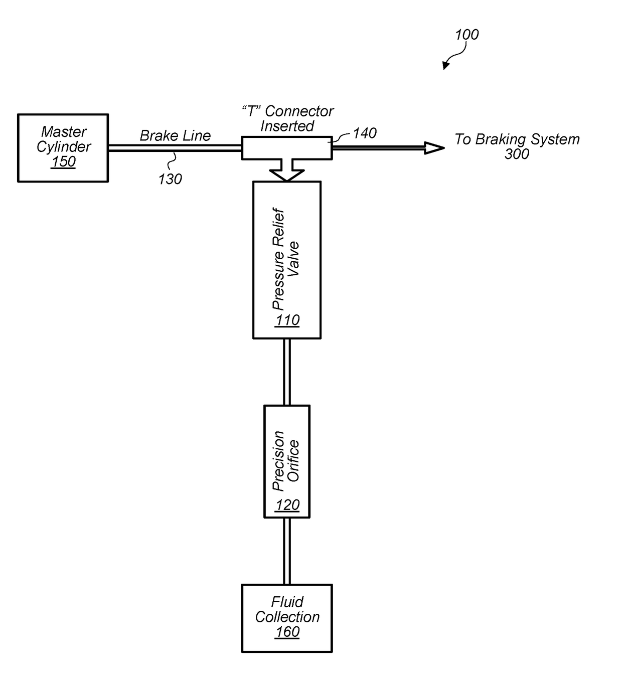
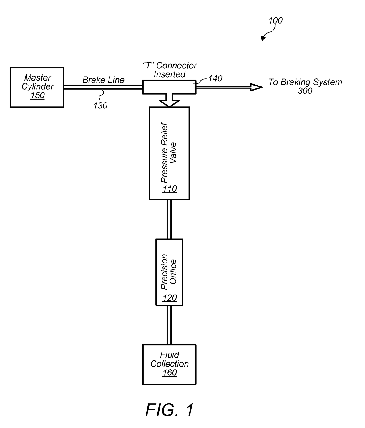
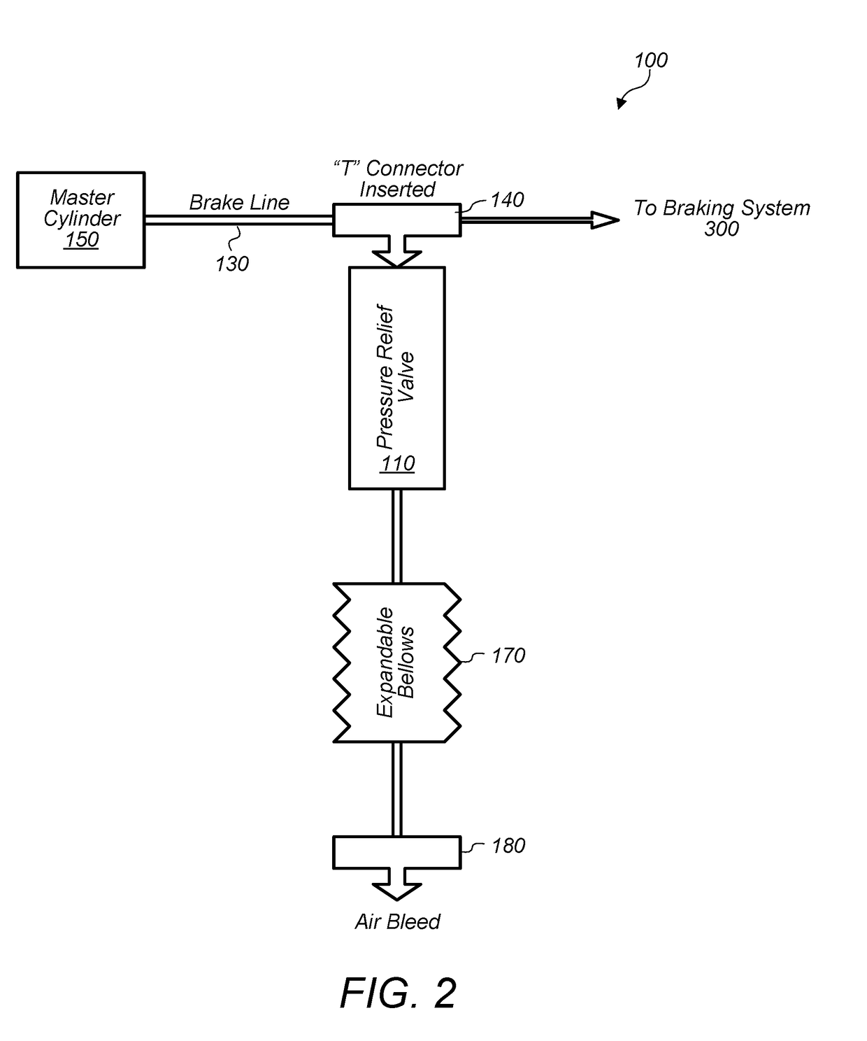
[0047]FIG. 1 depicts an embodiment of a system 100 for reducing backpressure in a braking system 300 including a valve 110 (e.g., a pressure relief valve) and a sized opening 120. The valve 110 may be coupled at any point along a pressurized brake line 130. The valve 110 may be coupled to the brake line using a fitting 140 (e.g., either during vehicle production or as part of an after market kit). A fitting may include a “T” fitting.

[0048]In some embodiment, a vehicle may include a system 100 installed for each master cylinder 150 of the vehicle. Current vehicle designs usually have two master cylinders, one for the front brakes and one for the rear brakes. Some braking systems use a cross-coupled configuration, wherein one master cylinder controls the left front and right rear wheel, and the other master cylinder controls the right front wheel and left rear wheel. So, each would have a system 100 coupled / installed for each master cylinder. In some embo...


PUM


Abstract

In some embodiments, a system and / or method may reduce certain injuries resulting from a vehicle collision. The method may include opening a valve in a pressurized brake line of a brake system of a vehicle in response to a trigger. The trigger may include a set pressure value of a fluid in the pressurized brake line. The method may include allowing the fluid in the pressurized brake line to flow through a sized opening accessible through the opened valve. The sized opening may reduce a fluid pressure in the pressurized brake line verses time. The sized opening may be dimensioned to allow a flow rate of the fluid conveying through the sized opening such that the fluid pressure reduces over a period of time. The method may include reducing backpressure on a brake pedal coupled to the pressurized brake line.

Description

PRIORITY CLAIM[0001]This application claims priority to U.S. Provisional Patent Application No. 62 / 495,197 entitled “HYDRAULIC PRESSURE RELIEF VEHICLE BRAKING SYSTEM” filed on Sep. 6, 2016, and U.S. Provisional Patent Application No. 62 / 482,418 entitled “PRESSURE RELIEF DESIGNS FOR VEHICLE BRAKING SYSTEM TO PREVENT INJURIES” filed on Apr. 6, 2017, both of which are incorporated by reference herein.BACKGROUND OF THE INVENTION1. Field of the Invention[0002]The present disclosure generally relates to vehicle safety systems. More particularly, the disclosure generally relates to systems and methods for reducing backpressure on brake pedals during a vehicular collision.2. Description of the Relevant Art[0003]Lower extremity injuries, in particular the foot / ankle are one of the most common in automotive crashes. Although not life threatening, they can lead to long term medical complications or permanent disability. In most cases foot and / or ankle fractures are caused during frontal automo...

Claims


Application Information

Patent Timeline
Patent Type & Authority Applications(United States)
IPC IPC(8): B60T7/06B60T13/68B60T13/66B60T13/58B60T15/36
CPCB60T7/065B60T13/68B60T13/662B60T13/581B60T15/36B60T2220/04B60T2270/88B60T7/22B60T13/683B60T13/686B60T17/18B60T2201/024
Inventor STOCKBAUER, FRED S.
Owner STOCKBAUER FRED S
Learn More