Methods and apparatus for spinal reconstructive surgery and measuring spinal length and intervertebral spacing, tension and rotation

a technology of intervertebral spacing and spinal reconstruction, applied in the field of spinal reconstruction surgery, can solve the problems of inadequate definition of vertical stability along the y-axis of the human spine, insufficient current products to provide full three-dimensional spinal re-alignment, and insufficient y-axis techniques, etc., and achieves better guidance and inadequate soft tissue release

Active Publication Date: 2018-05-10
MEDICREA INT SA
View PDF2 Cites 11 Cited by
  • Summary
  • Abstract
  • Description
  • Claims
  • Application Information

AI Technical Summary

Benefits of technology

[0016]Embodiments of the present invention allow the surgeon to measure the actual effect of the cage or spine manipulation on the middle column. Actual middle column height is measured including any changes in middle column height, along with angular changes. The output versus the idealized input may be provided. Conventional computerized mapping programs measure only the idealized introduction, e.g., of an 11 mm cage even though there is subsidence and it only increases the axial height at the middle column 9.5 mm. Subsidence is common as the vertebral bodies are osteoporotic and the cage might sink into the softer bone to some extent. In certain conventional procedures, a 30 degree hyperlordotic cage may yield a correction of 8.5 to 41.1 degrees, which may be an unacceptably wide variation and too unpredictable. Such systems only measure the idealized angles and do not measure the tension or the actual axial spinal

Problems solved by technology

Current products are not sufficient to provide full three-dimensional spinal re-alignment.
Current techniques do not account for the Y-axis, and the definition of vertical stability along the Y-axis of the human spine has not been adequately established.
Surgeons cannot rely on angles alone to restore three-dimension

Method used


Image

  • Methods and apparatus for spinal reconstructive surgery and measuring spinal length and intervertebral spacing, tension and rotation
  • Methods and apparatus for spinal reconstructive surgery and measuring spinal length and intervertebral spacing, tension and rotation
  • Methods and apparatus for spinal reconstructive surgery and measuring spinal length and intervertebral spacing, tension and rotation

Examples


Embodiment Construction

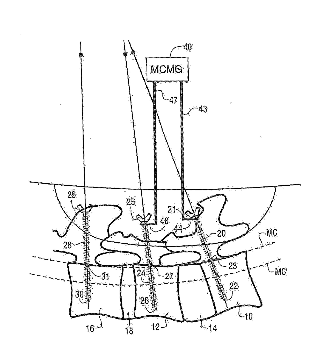
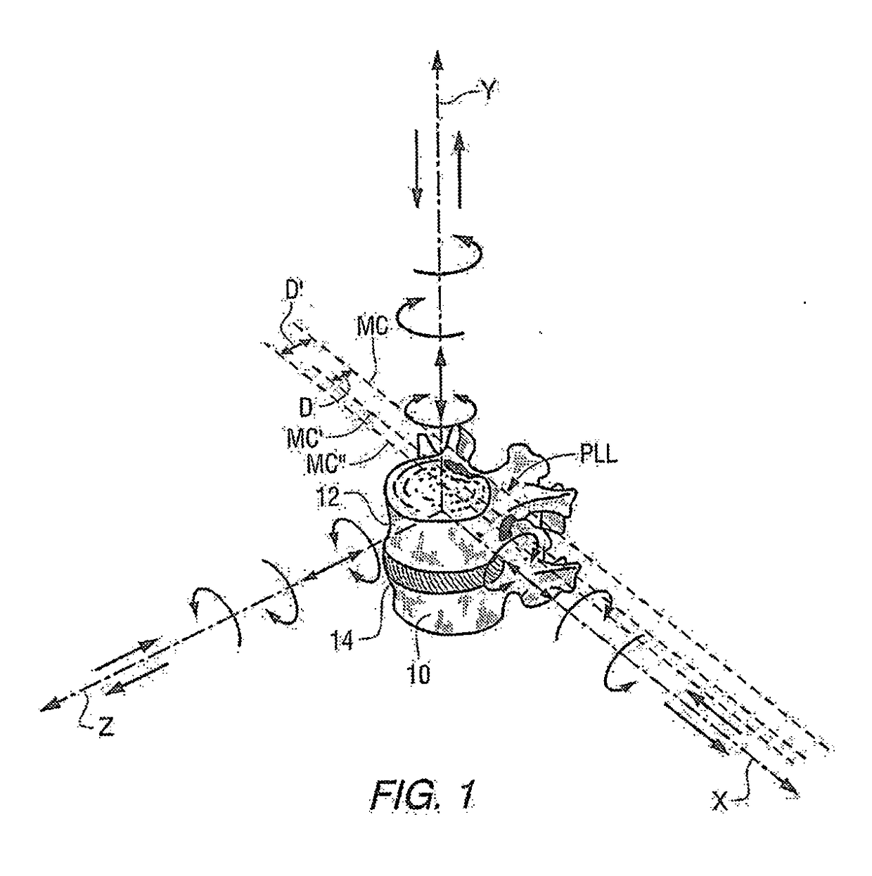
[0033]FIG. 1 is an isometric view illustrating two adjacent spinal vertebrae 10 and 12 separated by a spinal disk 14. Three axes have been labeled in FIG. 1, the X-axis, Y-axis, and Z-axis. The X-axis is oriented laterally from side-to-side of the patient. The Y-axis is oriented along the length of the spine. The Z-axis is oriented from front to back of the patient, i.e., the anterior-posterior direction. In accordance with embodiments of the present invention, spinal length along the Y-axis at the middle column may be measured, intervertebral spacing along the Y-axis at the middle column may be measured, intervertebral tension applied to the posterior longitudinal ligament along the Y-axis may be measured, the height of intervertebral spacers along the Y-axis at the middle column may be measured, intervertebral rotation around the Y-axis may be measured, and flexion-extension or anterior-posterior rotation around the X-axis may be measured.

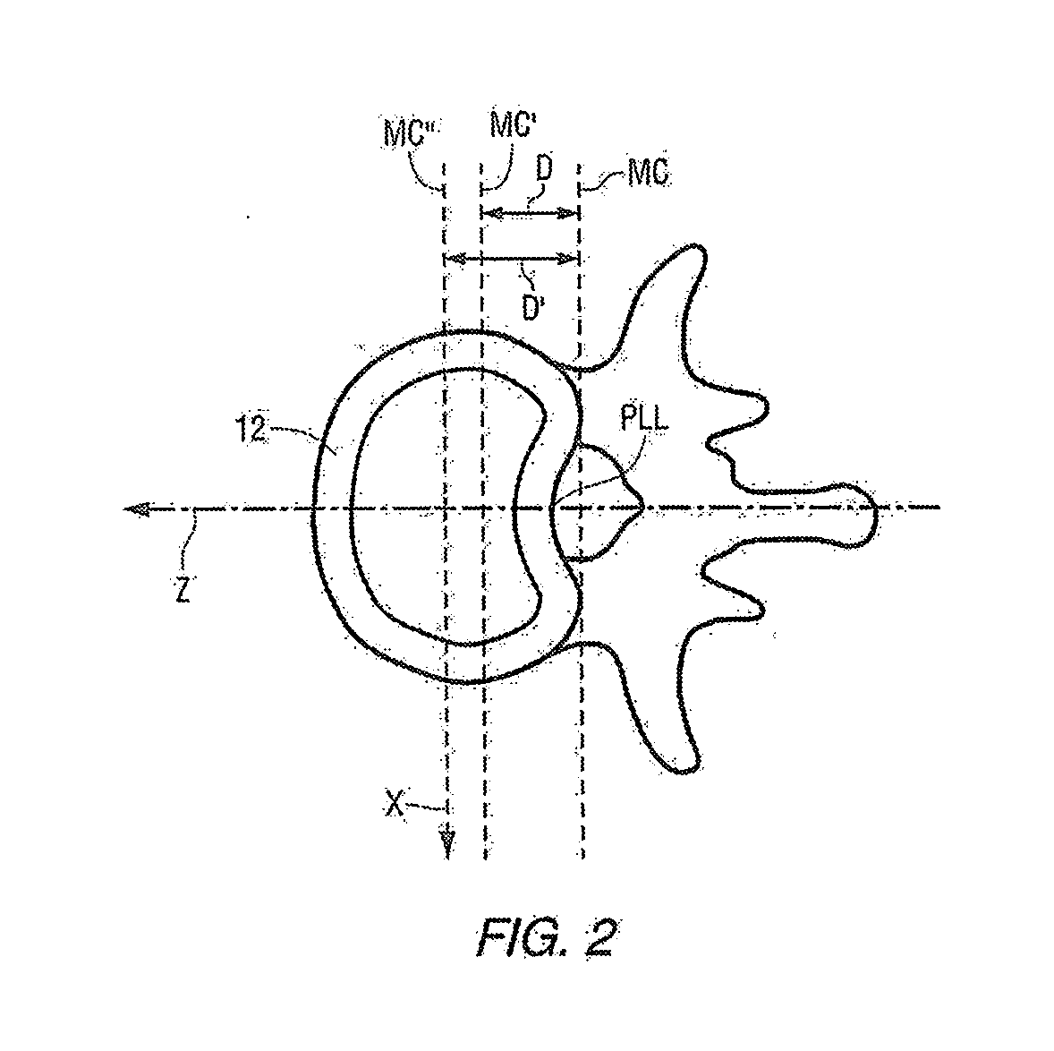
[0034]FIG. 2 is a top view of a spinal ver...


PUM


Abstract

Methods and apparatus are disclosed for performing spinal reconstructive surgery, including measuring spinal length in the Y-axis at the middle column, measuring intervertebral spacing in the Y-axis at the middle column, measuring intervertebral tension applied to the posterior longitudinal ligament, establishing the height of intervertebral spacers along the Y-axis at the middle column based on one or more of such measurements, measuring intervertebral rotation around the Y-axis, and measuring flexion-extension or anterior-posterior rotation around the X-axis.

Description

CROSS-REFERENCE TO RELATED APPLICATIONS[0001]This application claims the benefit of U.S. Provisional Patent Application Ser. No. 62 / 250,743 filed Nov. 4, 2015, and U.S. Provisional Patent Application Ser. No. 62 / 413,159 filed Oct. 26, 2016, both of which are incorporated herein by reference.FIELD OF THE INVENTION[0002]The present invention relates to methods and apparatus for spinal surgery, and more particularly relates to methods and devices for spinal reconstructive surgery, measuring spinal length and intervertebral spacing at the middle column, measuring intervertebral tension and establishing intervertebral spacer heights, and measuring intervertebral rotation.[0003]BACKGROUND INFORMATION[0004]Spinal reconstructive surgery may be used to correct anterior / posterior sagittal plane (Z-axis) imbalances ranging from abnormal (e.g., 40 mm) to severe (e.g., 90 mm) and / or to correct lateral coronal plane (X-axis) imbalances (e.g., greater than 20 mm). During such reconstructive surger...

Claims


Application Information

Patent Timeline
IPC IPC(8): A61B90/00A61B17/02A61B17/86
CPCA61B90/06A61B17/025A61B2090/067A61B2017/0256A61B2090/061A61B17/86A61B17/7077A61F2/4657A61B2090/064
Inventor MCAFEE, PAUL C.
Owner MEDICREA INT SA
Why Eureka
Try Eureka