Steering wheel unit, airbag module, and steering wheel body

a technology for steering wheel and airbag module, which is applied in the direction of road vehicles, vehicle components, pedestrian/occupant safety arrangements, etc., can solve the problems of large unit size, difficult production, and inability to manufacture axial positioning units entirely from plastic, and achieve the effect of reducing weigh

Active Publication Date: 2018-05-10
AUTOLIV DEV AB
View PDF4 Cites 1 Cited by
  • Summary
  • Abstract
  • Description
  • Claims
  • Application Information

AI Technical Summary

Benefits of technology

[0008]According to the present invention, the at least three support units are mutually separate elements. And thus, very little metal is needed, which firstly results in a reduction in weight. Furthermore, the comparatively small, separate support units are easy to produce.
[0010]In this case the supporting parts are disposed preferably on a perimeter side wall of the housing. This makes the assembly very simple.
[0012]With respect to the embodiment of the axial positioning units according to the present invention, the sections of the module-side positioning elements which are in contact with the positioning elements (hooks) on the steering wheel body-side, are preferably located, underneath the bottom of the housing, that is, relatively far away from the center of gravity. In order to obtain a precise radial positioning and to prevent unintentional movements of the module in the radial direction, in the region of each module-side axial positioning element it can be an advantage to provide an elastic radial positioning element extending radially from the side wall of the housing.
[0013]In a first, preferred embodiment, the support units are flexible, punched parts produced from sheet metal. Thus the support units can be very easily produced at low cost. In this case it is preferable that each support unit have two attachment sections which are formed by the ends of the piece of wire. In this case it is additionally preferred that the elastic, radial positioning means each extend between two parallel legs of the U-shaped regions of the support units, wherein the elastic radial positioning means can be a single piece with the housing.
[0014]In a second, preferred embodiment of the present invention, the support units are flexible punched parts produced from sheet metal. This has the particular advantage that the radial positioning elements can be designed as a single piece with the flexible, punched parts of the axial positioning elements.

Problems solved by technology

The housing generally consists mostly of plastic, however, due to the large forces occurring during an impact, as a rule it is not possible to manufacture the axial positioning units entirely from plastic.
The disadvantage of the above-described prior art is that a-the unit is relatively large and thus heavy and difficult to produce, and a flexible bending part of metal is needed for the housing bottom with the molded on lashings.

Method used


Image

  • Steering wheel unit, airbag module, and steering wheel body
  • Steering wheel unit, airbag module, and steering wheel body
  • Steering wheel unit, airbag module, and steering wheel body

Examples


second embodiment

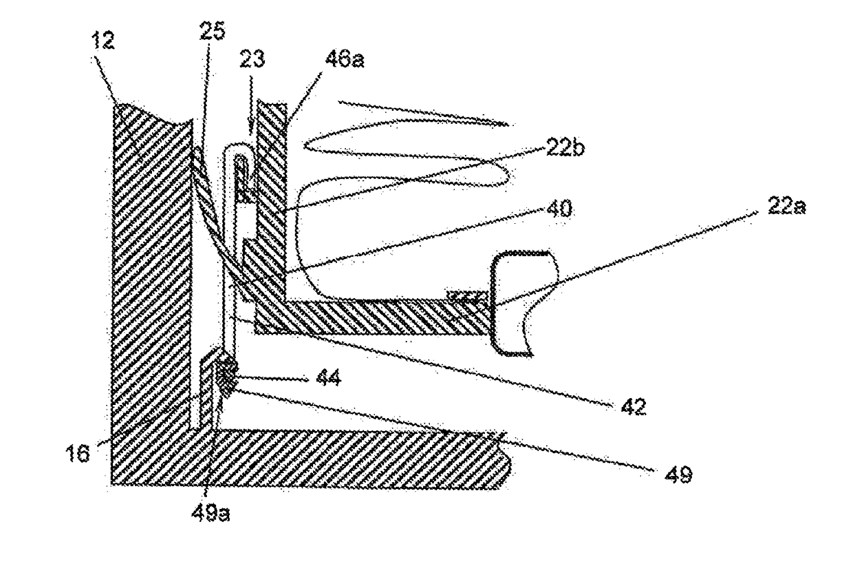
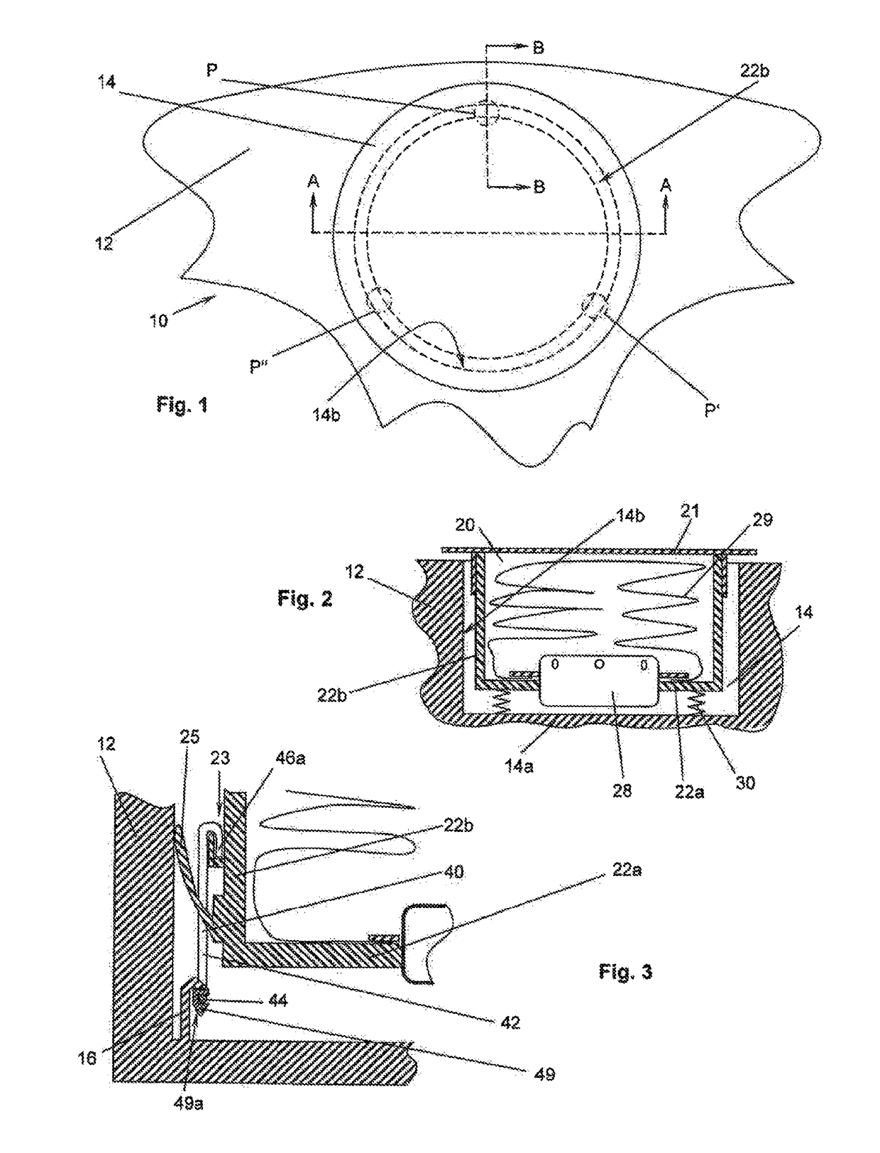
[0051]FIG. 11 depicts an axial positioning element 40 on the module side, in a representation corresponding to that of FIG. 10. FIG. 12 depicts the support unit 42 of this module-side axial positioning element 40. In contrast to the first exemplary embodiment, the support unit 42 here is a flexible, punched part with an O-shaped main section, a reinforcing arm 47 extending from the upper end of the O (wherein this reinforcing arm extends in the direction of the lower end of the O which forms the lower, U-shaped region 44), and an elastic radial positioning arm 48 of the support unit extending likewise from the upper end of the 0. To accommodate the connecting arm 47, the side wall 22b of the housing 22 features a corresponding, slotted receptacle.

[0052]At the U-shaped, lower region 44 of the support unit 42 there is disposed also a plastic element 49, wherein this depicted exemplary embodiment is created by overmolding of the U-shaped, lower region 44. In addition, the upper end of ...

first exemplary embodiment

[0059]FIGS. 22 and 23 show a second exemplary embodiment of the second design of the invention. The support units 142 here are designed as flexible punched parts made of sheet metal, in particular steel sheet metal, with an upper section 145 and an attachment region 146, wherein the upper section 145 and attachment region 146 stand preferably perpendicular to each other. The attachment region 146 features a hole for insertion of a screw 150 or of a bolt. A window 145a is punched into the upper section 145 so that it has a U-shaped, upper region 144. In the illustrated, preferred exemplary embodiments, a curved section 145b extends essentially horizontally from each of the upper edges of the window 145a, so that an enlarged contact surface area is obtained, in comparison to the simple edge. A protrusion of the housing engages in the window 145a (as in the first exemplary embodiment as well).

[0060]FIG. 24 shows a variation of the second exemplary embodiment. Here the attachment region...


PUM


Abstract

A steering wheel unit (10) for a motor vehicle having, a steering wheel body (12), an airbag module (20) accommodated in a hub region of the steering wheel body (12), which includes a housing (22), an inflator connected to the housing (22), and an airbag (29) folded into the housing (22), and at least three axial positioning units which define the axial position of the housing (22) when not pressed down with respect to the steering wheel body (12). Each of the three axial positioning units include an axial positioning element (40) connected on the module side to the housing (22), or an axial positioning element connected to the steering wheel body on the steering wheel body side, wherein the positioning element features a metal support unit (42). The at least three support units (42) are elements separate from each other.

Description

CROSS-REFERENCE TO RELATED APPLICATION[0001]This application is a 35 U.S.C. § 371 national phase application of International PCT Application No.: PCT / EP2016 / 058889, filed Apr. 21, 2016, which claims the benefit of priority under 35 U.S.C. § 119 to German Patent Application No.: 10 2015 005 281.0, filed Apr. 24, 2015.FIELD OF THE INVENTION[0002]The invention relates to a steering wheel unit for a motor, to an airbag module for use in one such steering wheel, and to a steering wheel body for use in one such steering wheel unit.BACKGROUND[0003]In nearly every modern passenger vehicle, an airbag module is accommodated in the hub region of the steering wheel, which features a housing, an inflator connected to the housing, usually in the form of a gas generator, and an airbag folded into the housing. The steering wheel body herein usually features a receptacle with a bottom and a side, inner wall. In the design known as the “floating module;” the housing is connected to the steering whee...

Claims


Application Information

Patent Timeline
Patent Type & Authority Applications(United States)
IPC IPC(8): B60R21/203
CPCB60R21/203B60R21/235B60Y2200/11B60R21/2037
Inventor JACQMARCQ, THIERRYGARRET, GILLESBAILLIVET, REMI
Owner AUTOLIV DEV AB
Why Eureka
Try Eureka