
Ceiling fan capable of adjusting angles of fan blades

a ceiling fan and angle adjustment technology, applied in the field of ceiling fans, can solve the problems of increasing the electric power consumption of the driving motor, and the regular user of the ceiling fan is unable to adjust the tilting angle of the fan blades by himself, and achieve the effect of optimizing the volume of air curren

Active Publication Date: 2018-05-10
ETEN TECH
View PDF4 Cites 34 Cited by
  • Summary
  • Abstract
  • Description
  • Claims
  • Application Information

AI Technical Summary

Benefits of technology

The patent text describes a device that saves power and makes the user more comfortable by optimizing the air current. When the motor rotates, the device allows the inner tube to move up or down, which in turn drives the outer tube to rotate. This results in an efficient use of air, which meets power saving requirements and allows for a constant speed of rotation. Overall, the device provides an improved user experience.

Problems solved by technology

Under a constant revolution speed, as the tilting angles of the fan blades increase, the volume of the air current and windage on the fan blades increase accordingly and output kinetic energy, and electric power consumption of the driving motor increase consequently.
However, since the conventional ceiling fan is suspended from the ceiling and the pin should be detached from one fan blade before adjusting the tilting angle of the fan blade, a regular user of the ceiling fan is unable to adjust the tilting angles of the fan blades by himself.

Method used


Image

  • Ceiling fan capable of adjusting angles of fan blades
  • Ceiling fan capable of adjusting angles of fan blades
  • Ceiling fan capable of adjusting angles of fan blades

Examples


Embodiment Construction

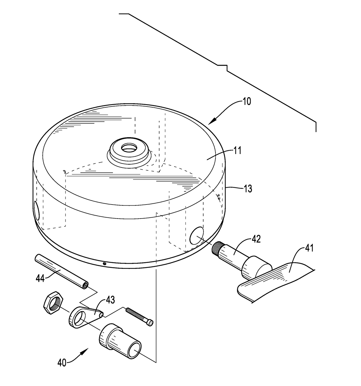
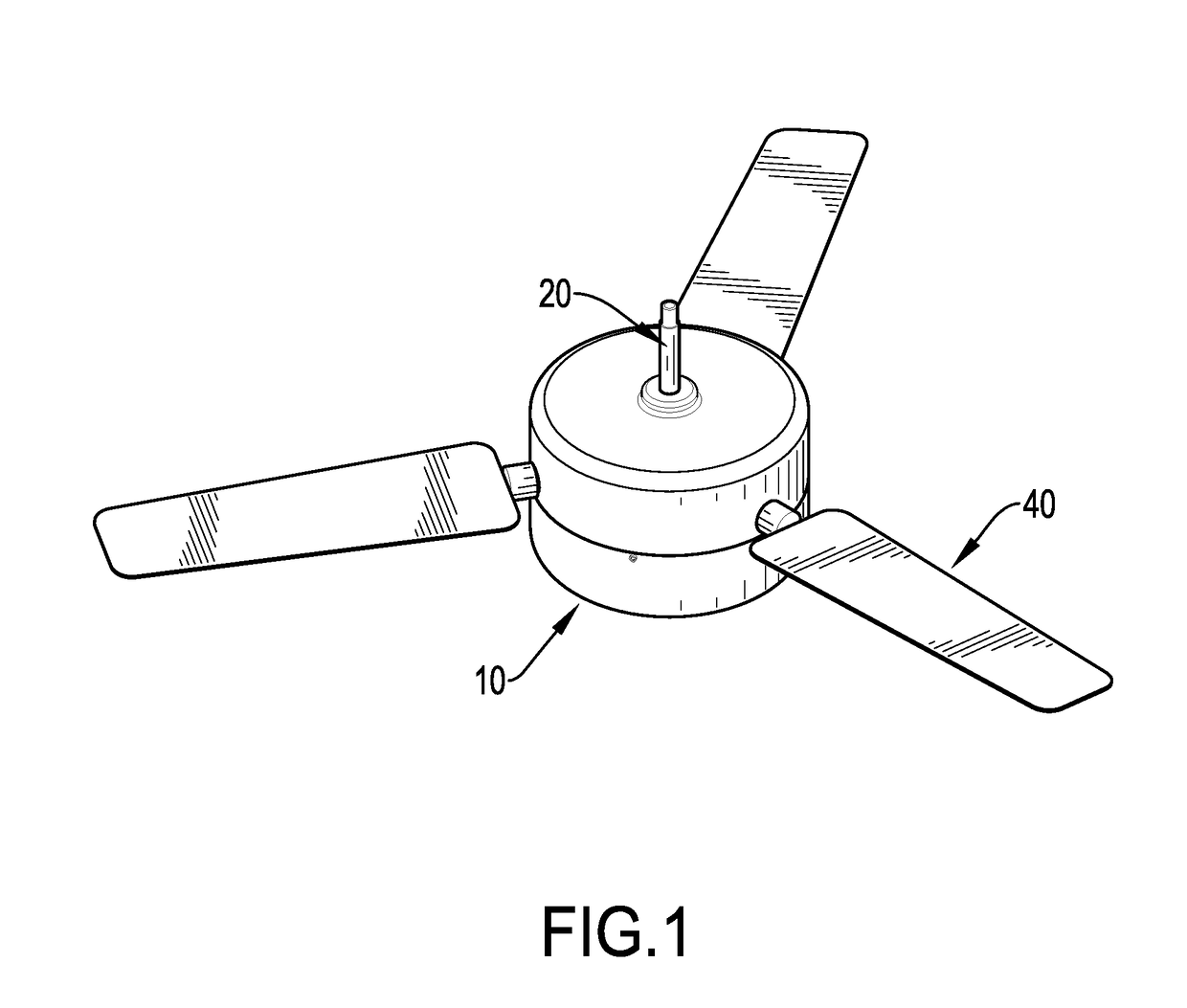
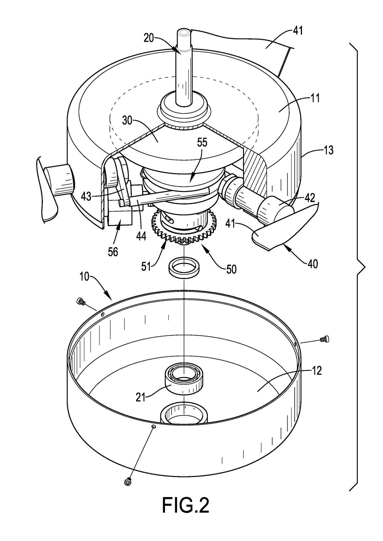
[0020]With reference to FIGS. 1 and 2, a ceiling fan in accordance with the present invention comprises a hub 10, a downrod 20, a rotating motor 30, multiple blade assemblies 40, and an adjusting assembly 50.

[0021]The hub 10 is hollow and has a top panel 11, a bottom panel 12, and a side panel 13. Specifically, the hub 10 is formed by attaching an upper casing and a lower casing. The upper casing has the top panel 11 and an upper sidewall. The lower casing has the bottom panel 12 and a lower sidewall. The upper sidewall and the lower sidewall are attached to each other to form the side panel 13.

[0022]With further reference to FIG. 5, the downrod 20 is vertically mounted through the hub 10 along a rotation axis of the hub 10 and is connected to the top panel 11 and the bottom panel 12 of the hub 10 via rotating bearings 21, such that the hub 10 can rotate relative to the downrod 20. The downrod 20 has a top end used for being fixed to a ceiling, so as to suspend the ceiling fan from ...


PUM


Abstract

A ceiling fan capable of adjusting angles of fan blades includes a hub, a downrod, a rotating motor selectively driving the hub to rotate relative to the downrod, multiple blade assemblies separately mounted on and arranged around the hub, and an adjusting assembly mounted in the hub and including an outer tube, an inner tube, a support, and a driving motor. A driving rod of each of the blade assemblies is mounted in a driving annular recess of the support. When a driving screw of the driving motor rotates, the driving screw drives the outer tube to rotate and drives the inner tube to move upwardly or downwardly accordingly, so as to provide an optimized volume of air current that meets power saving requirement under a constant revolution speed of the rotating motor.

Description

BACKGROUND OF THE INVENTION1. Field of the Invention[0001]The present invention relates to a ceiling fan, especially to a ceiling fan that is capable of adjusting angles of fan blades.2. Description of the Prior Art(S)[0002]A ceiling fan is a mechanical fan suspended from a ceiling of a room and includes a hub, multiple fan blades mounted on and arranged around the hub, and a rotating motor driving the hub as well as the fan blades to rotate. Each of the fan blades tilts relative to a plane that is formed by rotation of the fan blades. Thus, the fan blades push air to form an air current and to circulate air, so as to ventilate the room and dissipate heat around human bodies. Velocity and volume of the air current depend on tilting angles of the fan blades and revolution speed of the driving motor. Under a constant revolution speed, as the tilting angles of the fan blades increase, the volume of the air current and windage on the fan blades increase accordingly and output kinetic en...

Claims


Application Information

Patent Timeline
Patent Type & Authority Applications(United States)
IPC IPC(8): F04D27/00F04D25/08F04D29/36F04D29/32
CPCF04D27/002F04D29/325F04D29/362F04D25/088F04D29/36
Inventor CHIA, HUI-TSU
Owner ETEN TECH
Learn More