Burner Nozzle Configuration and its Use

a technology of burner nozzle and nozzle, which is applied in the direction of combustion types, lighting and heating apparatus, incinerator apparatus, etc., can solve the problems of known high temperature of gasses

Inactive Publication Date: 2018-05-10
TARIS HERMANUS JOHANNUS THEODORUS MARIA
View PDF3 Cites 0 Cited by
  • Summary
  • Abstract
  • Description
  • Claims
  • Application Information

AI Technical Summary

Benefits of technology

[0028]According to another aspect, the present invention relates to a use of a burner configuration, or a burner device, according to the present invention for cleaning a gas that comprises contaminants, comprising the steps of supplying to the burner nozzle a fuel and igniting same for obtaining a flame, such that the flame is directed into the cylinder and the gas to be cleaned is supplied via the entrance of the cone to the exit of the cone and is at least partially fed into the flame for heating and decomposing contaminants in said gas mixture. This use provides the advantages as mentioned above. The term “heating and decomposing” means that the contaminants are converted due to the high temperature or are oxidized by the oxyg...

Problems solved by technology

In addition to that, it is known to subject gasses ...

Method used


Image

  • Burner Nozzle Configuration and its Use
  • Burner Nozzle Configuration and its Use

Examples


Embodiment Construction

[0037]In the figures similar parts are referred to with the same reference numbers. However, for sake of ease of understanding, not all parts that are required for a practical embodiment are shown in the drawing.

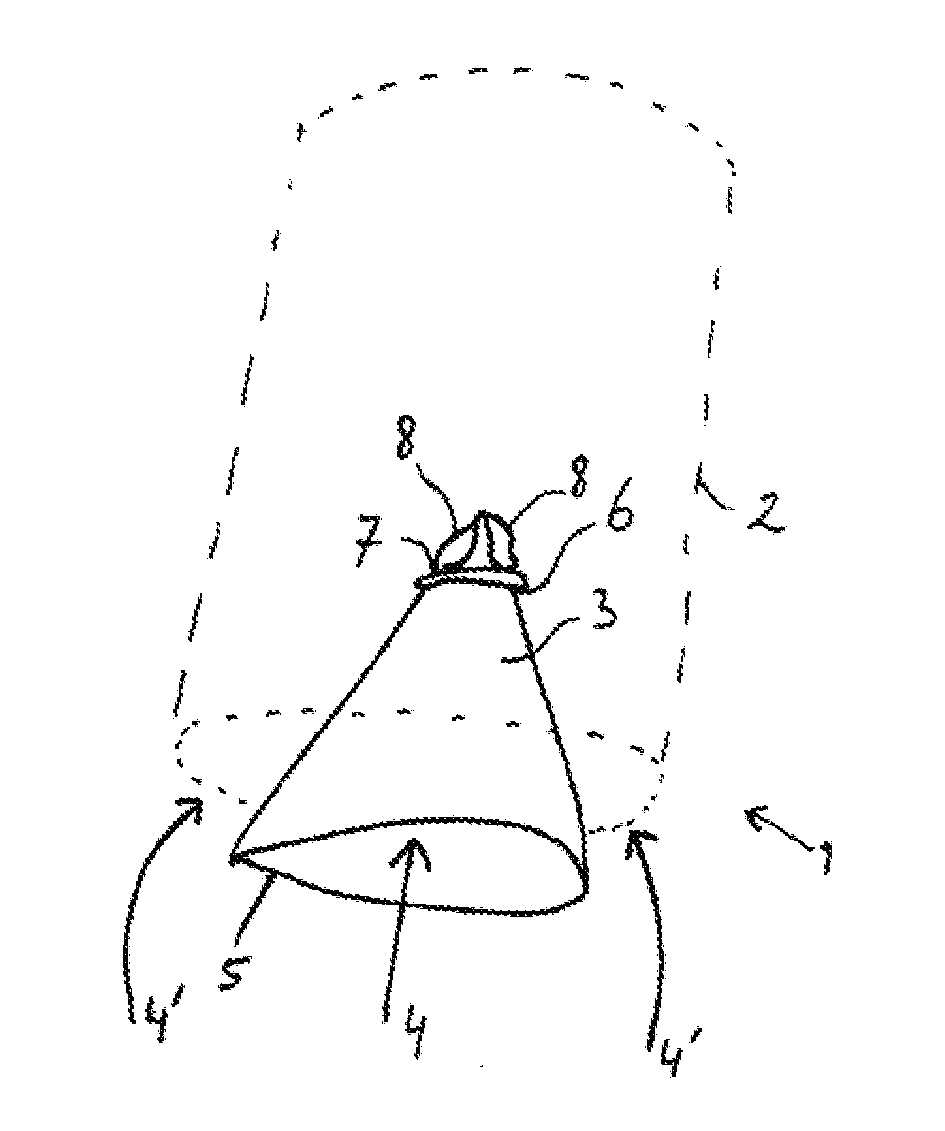
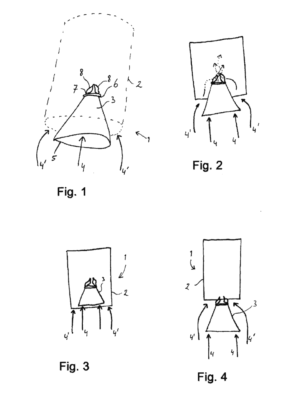
[0038]FIG. 1 shows a perspective view of a burner configuration, hereinafter also called burner 1, according to the present invention. The burner 1 comprises a (shown in dashed line) cylinder 2 and a cone 3, serving as a conductor for at least part of the gas mixture to be cleaned. The flow direction of the gas mixture to be cleaned is shown by means of arrows 4, 4′. Part of the gas mixture that is supplied through the cone is referred to by reference numeral 4, whereas part of the gas mixture that is supplied around the cone is referred to by reference number 4′. The cone 3 is positioned with its broad or wide side 5 relatively upstream and with the narrow side relatively downstream.

[0039]At the narrow side 6 a burner nozzle 7 is provided. At the burner nozzle a fuel is sup...


PUM


Abstract

The invention relates to a device for cleaning a gas mixture comprising contaminants. The device comprises a cylinder and a burner nozzle for supplying a fuel to be burned, said burner nozzle being embodied for directing into the cylinder a flame, wherein the flame is directed in a flow direction of the gas mixture. The device is characterized in that the device comprises cone shaped gas conductor with a relatively wide entrance for the gas mixture to be cleaned and a relatively narrow exit, The tapered shape is positioned in the flow direction and the narrow part of which is positioned near or within the supply side of the cylinder, with the proviso that the device is embodied for supplying into the cylinder the gas mixture to be cleaned partly through the cone shaped gas conductor and partly around the cone shaped gas conductor. The burner nozzle is positioned at the narrow side of the cone.

Description

CROSS-REFERENCE TO RELATED APPLICATIONS[0001]This application is a continuation application of Patent Cooperation Treaty Application No. PCT / NL2016 / 050485, filed on Jul. 6, 2016, which claims priority to Netherlands Patent Application No. 2015096, filed Jul. 6, 2015, and the specifications and claims thereof are incorporated herein by reference.STATEMENT REGARDING FEDERALLY SPONSORED RESEARCH OR DEVELOPMENT[0002]Not Applicable.INCORPORATION BY REFERENCE OF MATERIAL SUBMITTED ON A COMPACT DISC[0003]Not Applicable.STATEMENT REGARDING PRIOR DISCLOSURES BY THE INVENTOR OR A JOINT INVENTOR[0004]Not Applicable.COPYRIGHTED MATERIAL[0005]Not Applicable.BACKGROUND OF THE INVENTION[0006]The present invention relates to a burner configuration according to the preamble of claim 1.[0007]Such burner configuration or device is known in the art. For example, in burners for hot air balloons cylinders are used so as to be able to direct the flame into the balloon. The cylinder used for this purpose i...

Claims


Application Information

Patent Timeline
IPC IPC(8): F23G5/08F23D14/32F23D14/58F23G7/06
CPCF23G5/085F23D14/32F23D14/58F23G7/065F23G2204/103F23G2209/14F23C3/002F23D14/70F23G7/08
Inventor TARIS, HERMANUS JOHANNUS THEODORUS MARIA
Owner TARIS HERMANUS JOHANNUS THEODORUS MARIA
Why Eureka
Try Eureka