Extended signal paths in microfabricated sensors

a microfabricated sensor and signal path technology, applied in single device manufacturing, magnetic measurement, instruments, etc., can solve the problems of limiting the signal from the sensor, increasing the thickness of the cell body, and exacerbate the problem of the total heigh

Active Publication Date: 2018-05-10
TEXAS INSTR INC
View PDF4 Cites 31 Cited by
  • Summary
  • Abstract
  • Description
  • Claims
  • Application Information

AI Technical Summary

Benefits of technology

[0003]The following presents a simplified summary in order to provide a basic understanding of one or more aspects of the invention. This summary is not an extensive overview of the invention, and is neither intended to identify key or critic

Problems solved by technology

A drawback of this vertical component integration is the signal path through the alkali vapor is defined by the thickness of the cell body between the top and bottom plates of the optical cavity, which is commonly about 1 millimeter, undesirably limiting the signal from th

Method used


Image

  • Extended signal paths in microfabricated sensors
  • Extended signal paths in microfabricated sensors
  • Extended signal paths in microfabricated sensors

Examples


Embodiment Construction

[0013]The present invention is described with reference to the attached figures. The figures are not drawn to scale and they are provided merely to illustrate the invention. Several aspects of the invention are described below with reference to example applications for illustration. It should be understood that numerous specific details, relationships, and methods are set forth to provide an understanding of the invention. One skilled in the relevant art, however, will readily recognize that the invention can be practiced without one or more of the specific details or with other methods. In other instances, well-known structures or operations are not shown in detail to avoid obscuring the invention. The present invention is not limited by the illustrated ordering of acts or events, as some acts may occur in different orders and / or concurrently with other acts or events. Furthermore, not all illustrated acts or events are required to implement a methodology in accordance with the pre...


PUM


Abstract

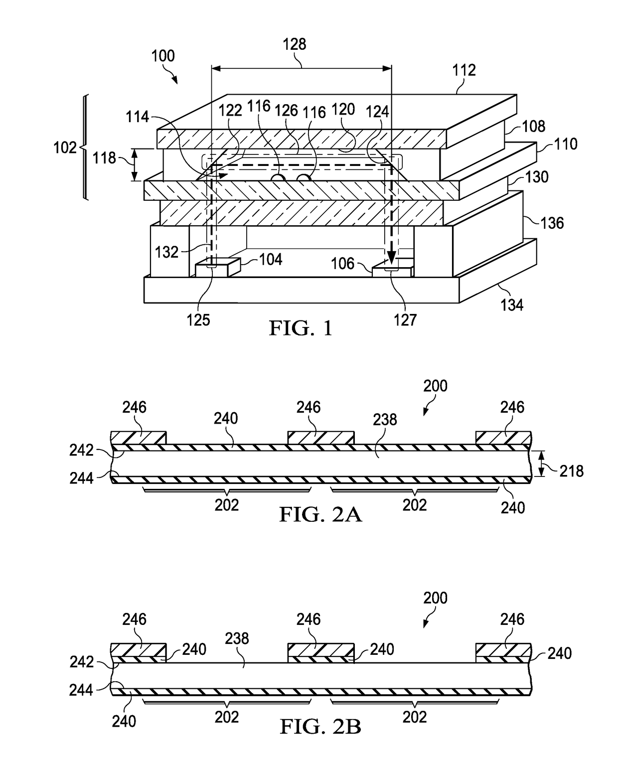
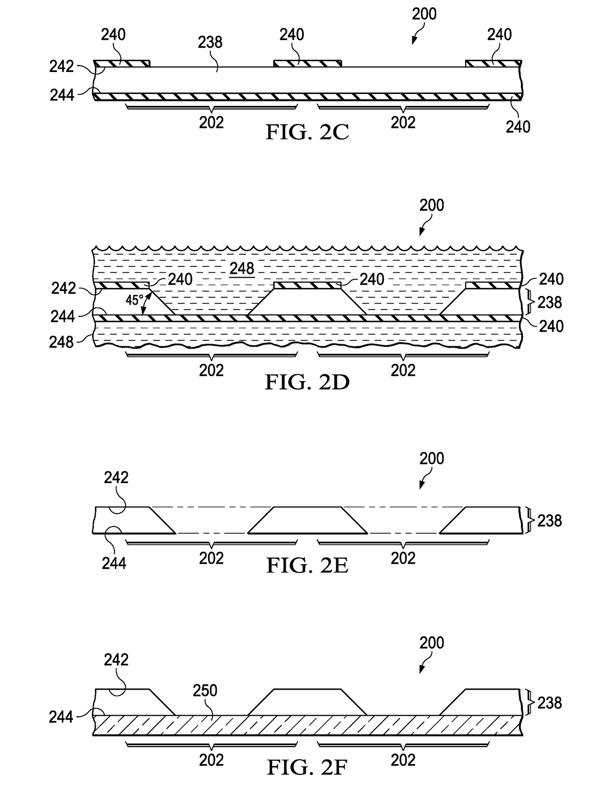
A microfabricated sensor includes a first reflector and a second reflector in a sensor cell, separated by a cavity path segment through a sensor cavity in the sensor cell. A signal window is part of the sensor cell. A signal emitter and a signal detector are disposed outside of the sensor cavity. The signal emitter is separated from the first reflector by an emitter path segment which extends through the signal window. The second reflector is separated from the second reflector by a detector path segment which extends through the signal window.

Description

FIELD OF THE INVENTION[0001]This invention relates to the field of microfabricated sensors.BACKGROUND OF THE INVENTION[0002]Microfabricated sensors such as microfabricated atomic clocks and microfabricated atomic magnetometers are efficiently assembled by vertically integrating the components. The laser signal source is typically located below the alkali vapor optical cavity; the optical cavity has windows for top and bottom plates to allow the laser light through. The photodetector is located over the optical cavity, so that the signal path extends vertically through the optical cavity. A drawback of this vertical component integration is the signal path through the alkali vapor is defined by the thickness of the cell body between the top and bottom plates of the optical cavity, which is commonly about 1 millimeter, undesirably limiting the signal from the sensor. Another drawback is that the total height of the microfabricated sensor is undesirably large, often precluding use in m...

Claims


Application Information

Patent Timeline
IPC IPC(8): G01R33/032G01R33/00G04F5/14
CPCG01R33/032G04F5/14G01R33/0052G01D5/26
Inventor PARSA, ROOZBEHFRENCH, WILLIAM
Owner TEXAS INSTR INC
Why Eureka
Try Eureka