Coil on plug signal detection

a coil-on-plug and signal detection technology, which is applied in the direction of mechanical equipment, machines/engines, instruments, etc., can solve the problems of inability of the engine control computer to make cylinder-to-cylinder variations in ignition timing, inability to adapt conventional test probes to coil-on-plugs, and inability to detect or obtain ignition signals from coil-on-plug devices. simple and accurate detection and detection

Inactive Publication Date: 2002-05-28
SNAP ON INC
View PDF12 Cites 75 Cited by
  • Summary
  • Abstract
  • Description
  • Claims
  • Application Information

AI Technical Summary

Problems solved by technology

A disadvantage of waste spark design is that an engine control computer cannot make cylinder-to-cylinder variations in the ignition timing.
However, conventional test probes are not adaptable to coil-on-plugs.
There is no accurate, simple way to detect or obtain an ignition signal from a coil-on-plug device.
In this approach, though, noise is a significant problem.
Further, there is no way to adjust the level of the signal input to account for differences in voltage output and other parameters of different coils and distributors.
The Capek probe is prone to overloading or saturating the input circuitry of the oscilloscope or other test device.
This causes the device to display inaccurate signal waveforms and can damage the device.
However, modern handheld signal analyzers normally do not have such gain controls and require input signals to have an amplitude within a predictable narrow range.

Method used


Image

  • Coil on plug signal detection
  • Coil on plug signal detection
  • Coil on plug signal detection

Examples


Embodiment Construction

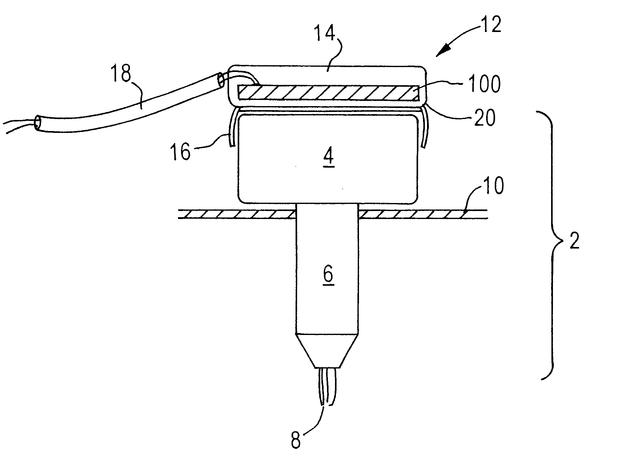
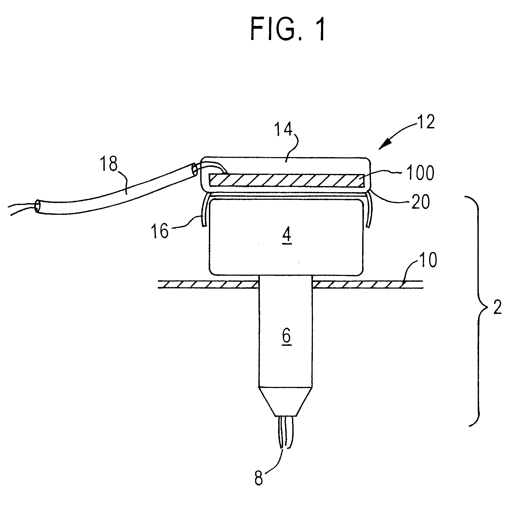
FIG. 1 is a side elevation, part section view of a signal detector mounted to a coil on plug.

Coil on plug 2 generally comprises a spark coil 4 integrally mounted on spark plug 6, which protrudes into and is mounted in cylinder 10 and terminates in spark gap 8. Coil 4 conducts transformed, high voltage direct current to spark plug 6 using internal connections. Coil 4 receives low voltage direct current via a wiring harness that has a distal end coupled to a primary coil of coil 4 and a proximal end coupled to a battery. Coil on plug devices that are suitable for use in this context are commercially available from AC Delco.

Signal detector assembly 12 is mounted on coil 4 for measurement of signal characteristics of signals or current generated by a secondary coil of coil 4. Generally, signal detector assembly 12 comprises probe housing 14, sensor 100, mounting clips 16, and cable 18. The probe housing 14 encloses and protects sensor 100 from the exterior environment which, in a motor ...


PUM


Abstract

An apparatus for measuring ignition charge signals produced by coils of coil-on-plug devices of an internal combustion engine. A signal detector comprises an insulating substrate having a first conductive planar layer on a first side and a second conductive planar layer on a second side. The first layer is coupled to a signal wire and the second layer is coupled to a ground wire. When the signal detector is held in close proximity to the coil of the coil-on-plug, ignition signals generated by the coil and passing to the plug are detected. The detected signals may be coupled to a signal analyzer for display and analysis. The amplitude of the signal that is output by the signal detector may be adjusted to different coils having different output signal strengths by modifying the ratio of the surface areas of the first layer and the second layer.

Description

The invention relates generally to test equipment useful in diagnosing internal combustion engines. The invention relates more specifically to a signal detector apparatus that can detect coil ignition signals from a coil-on-plug device.DESCRIPTION OF RELATED ARTInternal combustion engines of the type commonly used in motor vehicles operate by igniting combustible gases in one or more cylinders using assistance from an ignition coil. The ignition coil has two windings: a low-voltage primary winding, and a high-voltage secondary winding. The windings cooperate to transform 12 volts D.C. from the battery into high voltage of 4,000 volts or more that is used by the spark plugs to ignite the air-fuel mixture inside the cylinders.In a multi-cylinder engine, a distributor is used to couple ignition coil voltage to a plurality of spark plugs. The ignition coil output voltage is coupled to the center of the distributor. The distributor sends spark voltage to each spark plug at the proper tim...

Claims


Application Information

Patent Timeline
Patent Type & Authority Patents(United States)
IPC IPC(8): F02P3/02F02P17/12F02P17/08F02P17/00
CPCF02P3/02F02P17/12F02P2017/125F02P2017/003F02P17/00
Inventor FONG, CHEE K.BRYANT, ROBERT R.NORMILE, JAMES M.MCQUEENEY, KENNETH A.SPENCER, TIMOTHY J.
Owner SNAP ON INC
Why Eureka
Try Eureka