Method and apparatus for determining diffusible hydrogen concentrations

a technology of diffusible hydrogen and concentration, which is applied in the direction of calibration apparatus, instruments, specific gravity measurement, etc., can solve the problems of material unsafe or unsatisfactory use, material is considered unsafe or unsatisfactory, and the effect of less time and reliable and accura

Inactive Publication Date: 2007-12-11
ALLIANCE FOR SUSTAINABLE ENERGY
View PDF23 Cites 35 Cited by
  • Summary
  • Abstract
  • Description
  • Claims
  • Application Information

AI Technical Summary

Benefits of technology

[0010]It is a more specific object of the present invention to provide a portable, easy-to-use method and apparatus for use in performing field or on-site diffusible hydrogen concentration measurements on an object and / or structure.
[0013]It is yet another specific object of the present invention to provide a reliable and accurate method and apparatus for use in measuring diffusible hydrogen concentrations in an object and / or structure in less time than is currently possible.

Problems solved by technology

High concentrations of hydrogen dissolved in construction and fabrication materials are an ongoing concern because hydrogen concentrations can alter the mechanical properties of the materials causing cracking, embrittlement, weakening, and other detrimental changes.
Generally, there is an acceptable concentration of introduced or dissolved hydrogen for each material above which the material is considered unsafe or unsatisfactorily weak for its intended use.
While such methods of measuring the volume of diffusible hydrogen in samples provide relatively accurate measurements of the diffusible hydrogen content in each sample, they do have a number of significant limitations and problems.
First, these methods measure bulk or total diffusible hydrogen evolving from the sample and do not provide a method of identifying concentrations of hydrogen or, more particularly, localized concentrations of hydrogen.
Such, localized concentrations of hydrogen, when combined with residual stresses at inclusions, grain boundaries, or the weld fusion lines, can cause cracks to occur even though overall diffusible hydrogen for a bulk sample may be below allowable content limits.
Localized concentrations of hydrogen often occur more readily in higher strength steels, which have a lower allowable hydrogen content limit, e.g., as low as 1 to 2 ml / 100 g. Second, these current standard methods do not lend themselves to nondestructive field or in-place testing of welded joints in components and structures.
If a welder does not precisely follow the welding procedure due to poor training or other causes, the resulting welded joints in actual machinery, pipelines, or other unacceptable welded objects would not be detectable with these methods, which may leave welded joints intended for use that have undetected hydrogen concentrations above the allowable limits and may fail catastrophically.
Fourth, these methods are expensive and time consuming.
Some efforts have been made to develop sensors for other applications that detect the presence of hydrogen but are not useful in measuring the concentration of hydrogen.
While providing initial detection of the presence of a small amount of hydrogen in the general volume surrounding the sensor, this leak detector is not useful for accurately measuring diffusible hydrogen concentrations in a material sample for identifying potential hydrogen damage.

Method used


Image

  • Method and apparatus for determining diffusible hydrogen concentrations
  • Method and apparatus for determining diffusible hydrogen concentrations
  • Method and apparatus for determining diffusible hydrogen concentrations

Examples


Embodiment Construction

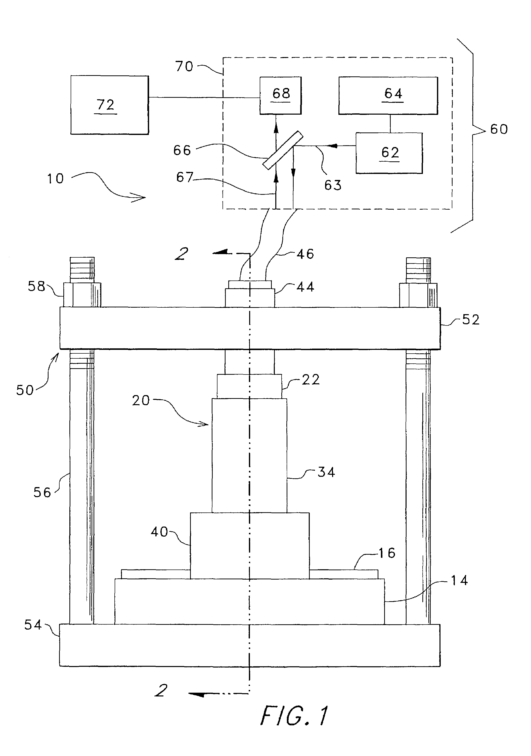
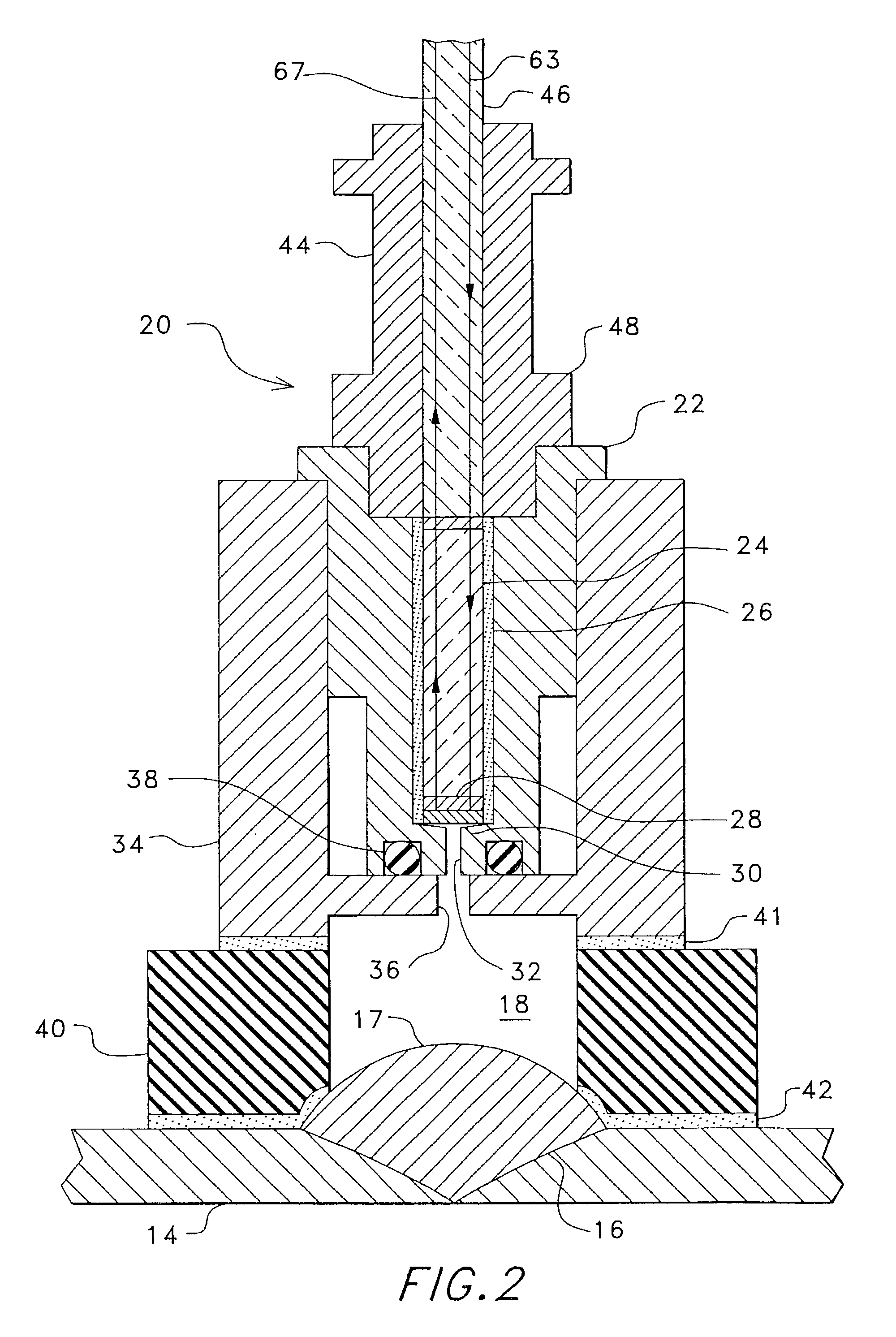
[0023]A diffusible hydrogen measuring apparatus 10 for use in measuring diffusible hydrogen concentrations according to the present invention is illustrated in FIG. 1 mounted with a mounting device 50 on a welded object 14 comprising pieces of steel joined with weld bead 16 from a standard arc welding process. Although the present invention is useful for measuring diffusible hydrogen concentration in many structures, such as cannon barrels, pressure vessels, and galvanically protected metal structures, the following description will generally be directed to welded structures, and specifically, welded joints on steel structures, to more fully and clearly describe the inventive features of the present invention. Persons skilled in the art will, upon understanding this description, recognize the applicability of the invention for use on such other structures and will be able to apply this invention for such uses.

[0024]The hydrogen measuring device 10 includes a sensor assembly 20 that ...


PUM

PropertyMeasurementUnit
wavelengthaaaaaaaaaa
thicknessaaaaaaaaaa
diffusion coefficientaaaaaaaaaa

Abstract

A measuring apparatus and method for use in measuring diffusible hydrogen concentrations in materials, structures, and other objects. In an embodiment of the invention for use in welding applications, the measuring apparatus (10) includes a sensor assembly (20) that, with an included sealing member (40), defines a sample area (17) on a weld bead (16) from which hydrogen evolves into a sample volume (18) defined by the sealing member (40), a sensor housing (34) and a sensor (22) of the sensor assembly (20). The hydrogen reacts with a sensing layer (28) and a reflector layer (30) positioned on the end of an optical fiber (24), all of which are included in the sensor assembly (20) and are sealably positioned within the sensor (22). The sensing layer (28) comprises a chemochromic material that undergoes changes in physical properties, such as optical transmission properties, when it reacts with hydrogen and these changes are measured by the measuring apparatus (10) to determine the amount of hydrogen evolving from the sample area (17). An optical fiber (46) is joined to the sensor optical fiber (24) to direct light (63) transmitted by a light source (62) in a hydrogen monitoring assembly (60) through the sensing layer (28) to strike the reflector layer (30) which reflects light (67) back through optical fiber (46) to a detector (68) in the hydrogen monitoring assembly (60). A signal analyzer (72) is included in the hydrogen monitoring assembly (60) and is calibrated and configured to measure the diffusible hydrogen concentration in the weld bead (16) based on measured changes in the optical transmission properties of the sensing layer (28).

Description

CROSS-REFERENCE TO RELATED PATENT APPLICATIONS[0001]This application claims the benefit of U.S. Provisional Application Ser. No. 60 / 138,144, filed Jun. 8, 1999.TECHNICAL FIELD[0002]The present invention relates generally to a method and apparatus for determining diffusible hydrogen concentrations in a material sample, and more particularly, to a method and apparatus that converts measured changes in the physical properties, such as optical absorption, of a sensor element into an output signal that is closely correlated to the diffusible hydrogen content of the sample.BACKGROUND ART[0003]High concentrations of hydrogen dissolved in construction and fabrication materials are an ongoing concern because hydrogen concentrations can alter the mechanical properties of the materials causing cracking, embrittlement, weakening, and other detrimental changes. Hydrogen may be introduced into materials by a number of processes including, for example, arc welding, extended exposure to pressurized...

Claims


Application Information

Patent Timeline
Patent Type & Authority Patents(United States)
IPC IPC(8): G01D18/00B32B5/02G01N21/00G01N27/00G01N3/62G01N31/00G01N33/00G01N33/20G01N33/497G01N35/00G01N37/00G01N7/00G01N9/00G01R35/00G01S7/40G01W1/18G12B13/00
CPCG01N21/783G01N33/203Y10T436/22G01N2001/2241G01N33/2025
Inventor BENSON, DAVID K.WILDEMAN, THOMAS R.SMITH, R. DAVISOLSON, DAVID L.
Owner ALLIANCE FOR SUSTAINABLE ENERGY
Why Eureka
Try Eureka