
Multi-resolution switched audio encoding/decoding scheme

A technology of audio encoder and audio decoder, which is applied in the field of audio encoding and can solve problems such as poor quality and voice signal quality

Active Publication Date: 2011-09-07
FRAUNHOFER GESELLSCHAFT ZUR FOERDERUNG DER ANGEWANDTEN FORSCHUNG EV +1
View PDF7 Cites 35 Cited by
  • Summary
  • Abstract
  • Description
  • Claims
  • Application Information

AI Technical Summary

Problems solved by technology

However, speech signal quality at low bit rates is problematic
[0007] Speech coding schemes exhibit high quality for speech signals even at low bit rates, but poor quality for other signals at low bit rates

Method used


Image

  • Multi-resolution switched audio encoding/decoding scheme
  • Multi-resolution switched audio encoding/decoding scheme
  • Multi-resolution switched audio encoding/decoding scheme

Examples


Embodiment Construction

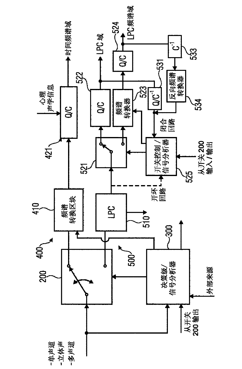
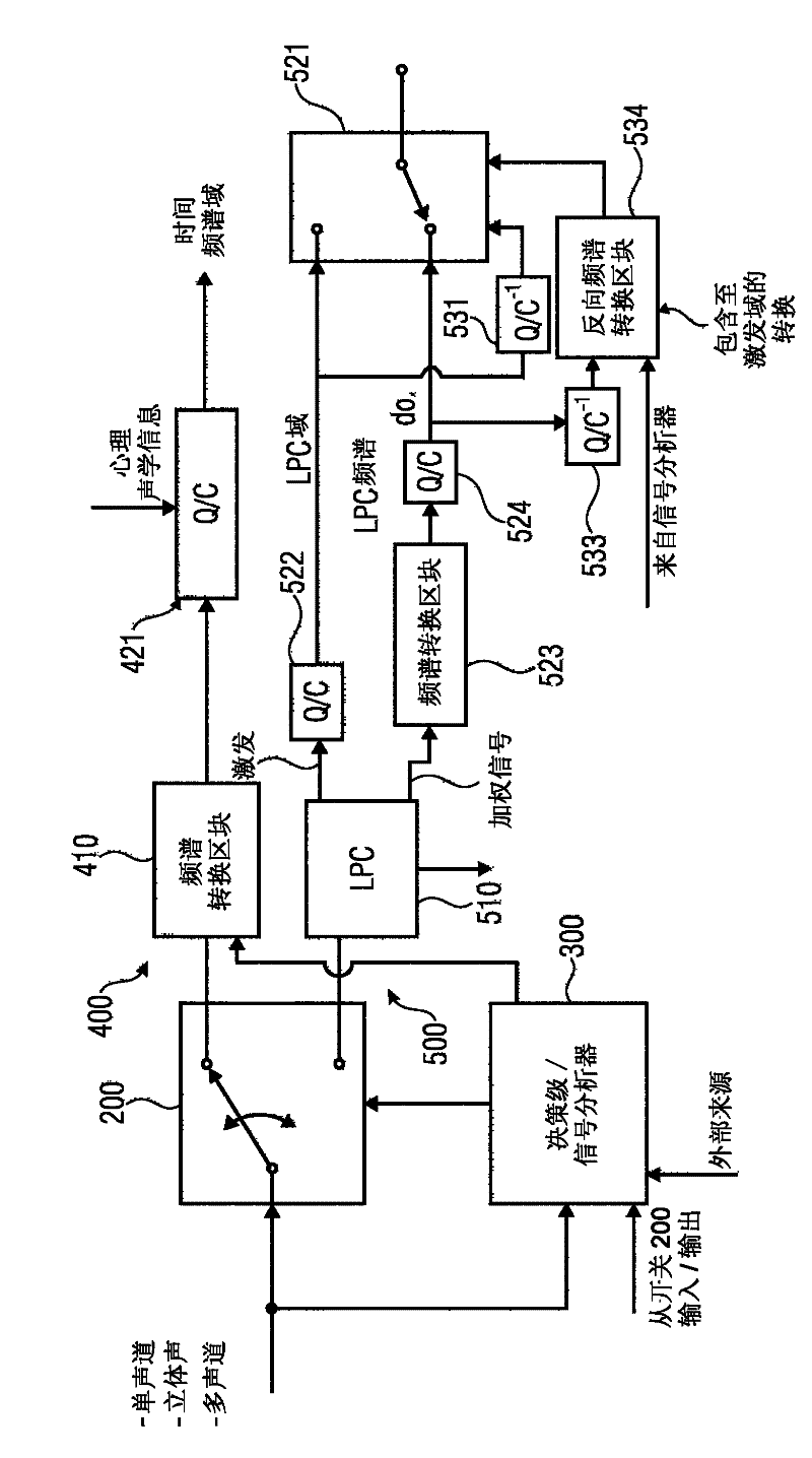
[0059] Figure 11A An embodiment of an audio encoder for encoding an audio signal is described. The encoder comprises a first encoding branch 400 for encoding an audio signal using a first encoding algorithm to obtain a first encoded signal.

[0060] The audio encoder also includes a second encoding branch 500 for encoding an audio signal using a second encoding algorithm to obtain a second encoded signal. The first encoding algorithm is different from the second encoding algorithm. Additionally, a first switch for switching between the first encoding branch and the second encoding branch is provided such that for a part of the audio signal, either the first encoding signal or the second encoding signal In an encoder output signal 801.

[0061] exist Figure 11A The audio encoder described in additionally comprises a signal analyzer 300 / 525, the signal analyzer 300 / 525 is configured to analyze a part of the audio signal to determine the output signal 801 of the audio signa...


PUM


Abstract

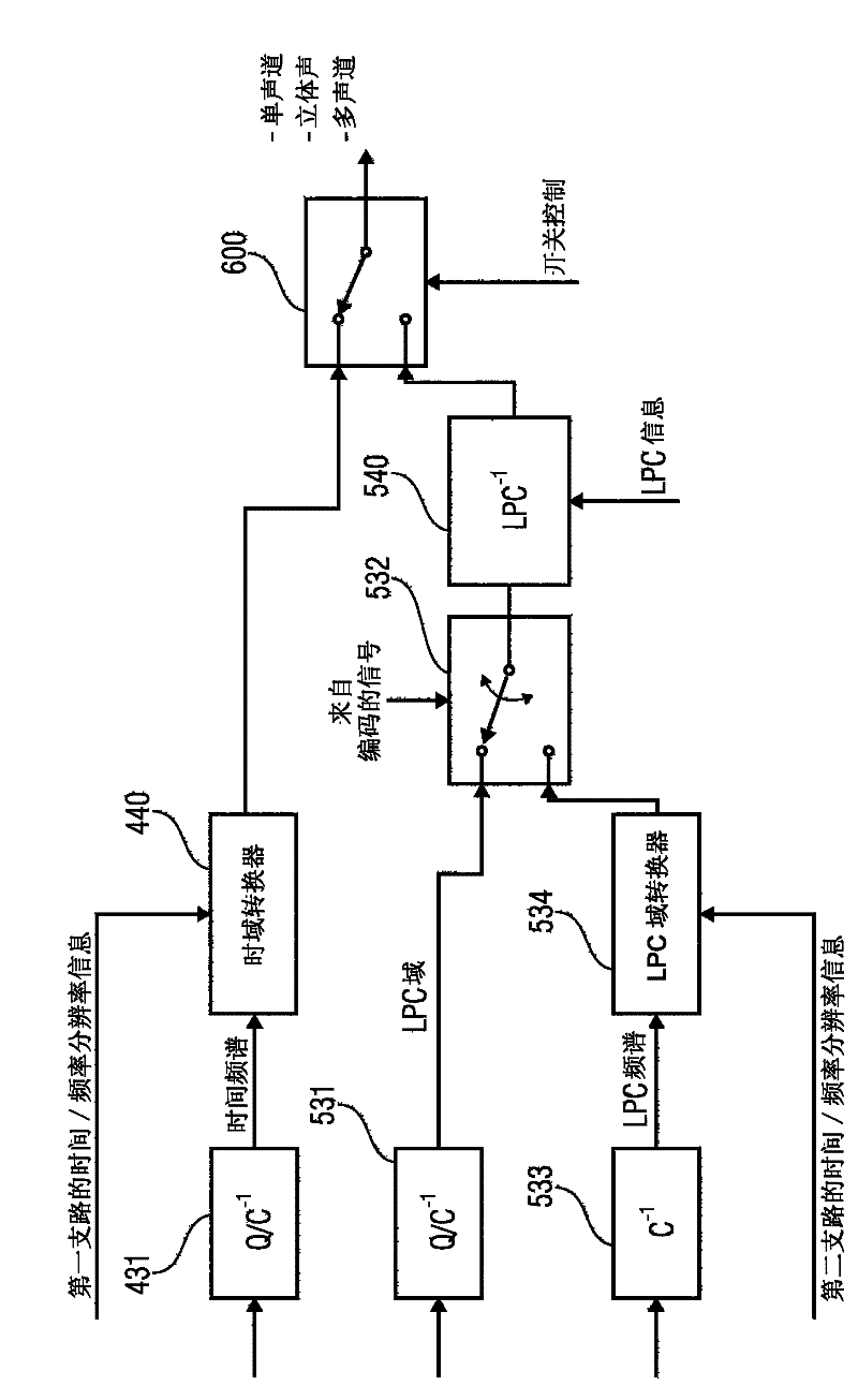
An audio encoder for encoding an audio signal comprises a first coding branch (400), the first coding branch comprising a first converter (410) for converting a signal from a time domain into a frequency domain. Furthermore, the audio encoder comprises a second coding branch (500) comprising a second time / frequency converter (523). Additionally, a signal analyzer (300 / 525) for analyzing the audio signal is provided. The signal analyzer, on the hand, determines whether an audio portion is effective in the encoder output signal as a first encoded signal from the first encoding branch or as a second encoded signal from a second encoding branch. On the other hand, the signal analyzer determines a time / frequency resolution to be applied by the converters (410, 523) when generating the encoded signals. An output interface includes, in addition to the first encoded signal and the second encoded signal, a resolution information identifying the resolution used by the first time / frequency converter and used by the second time / frequency converter.

Description

technical field [0001] The present invention relates to audio coding, and in particular to low bit rate audio coding schemes. Background technique [0002] Frequency domain coding schemes such as MP3 or AAC are known in the prior art. These frequency-domain encoders are based on a time-domain / frequency-domain conversion, a subsequent quantization stage, and an encoding stage, wherein in the subsequent quantization stage information from a perceptual module is used to control the quantization error, in which In the encoding stage, the quantized spectral coefficients and corresponding side information are entropy encoded using an encoding table. [0003] On the other hand, there are coders that are well suited for speech processing, such as AMR-WB+ described in 3GPP TS 26.290. Such speech coding schemes perform a linear predictive (LP) filtering of a time-domain signal. The LP filtering is obtained from a linear predictive analysis of the input time domain signal. The resu...

Claims


Application Information

Patent Timeline
IPC IPC(8): G01L19/02G10L19/14G10L19/022G10L19/24
CPCG10L19/24G10L19/022G10L19/02G10L19/04G10L19/18
Inventor 马克思·纽恩多夫斯特凡·拜尔耶雷米·勒科米特纪尧姆·福奇斯朱利安·罗比利亚德尼古劳斯·雷特尔巴赫福雷德里克·纳格尔拉尔夫·盖尔马库斯·穆赖特鲁斯伯恩哈德·格里菲利普·古尔纳伊雷德万·萨拉米
Owner FRAUNHOFER GESELLSCHAFT ZUR FOERDERUNG DER ANGEWANDTEN FORSCHUNG EV
Learn More