Signal testing system

a signal testing and signal technology, applied in the direction of transmission, transmission monitoring, electrical equipment, etc., can solve the problems of slow speed applications, low probability of intercept, and high cost of configuration to perform test measurements, and achieve the effects of low cost, low probability of intercept, and high cos

Inactive Publication Date: 2006-11-09
ARCADYAN
View PDF3 Cites 35 Cited by
  • Summary
  • Abstract
  • Description
  • Claims
  • Application Information

AI Technical Summary

Benefits of technology

[0019] In another preferred embodiment of the invention, the signal analyzer further comprises: an amplifier, connected to the first duplexer for amplifying the signals transmitted therefrom; a signal receiver, connected to the amplifier, capable of power dividing, filtering and converting the signals outputted from the amplifier; a switch control, connected to the signal receiver, capable of power dividing the signals transmitted from the signal receiver while selectively switching on / off the conducting of the divided signals so as to generate a plurality of combined signals, each being formed by selectively combining at least a divided signal selected from the group of the conducting signals; and a signal processor, for receiving and analyzing the plural combined signals.
[0020] Moreover, in a preferred embodiment of the invention, the signal testing system further comprises: a signal synthesizer, for generating a pulse signal; and a second duplexer, connected to the signal synthesizer, for enabling a situation selected from one of the following: transmitting the pulse signal to the first multiplexer for using the same as the signal outputted from the reference device, and transmitting the pulse signal to the second multiplexer for using the same as the signal outputted from the device-under-test. Wherein, the signal synthesizer further comprises: a signal generator; a switch control, connected to the signal generator for receiving a plurality of signals outputted from the same, capable of power-dividing the plural signals transmitted from the signal generator while selectively switching on / off the conducting of the divided signals so as to generate a plurality of combined signals, each being formed by selectively combining at least a divided signal selected from the group of the conducting signals; a signal transmitter, for receiving the signals outputted from the switch control so as to perform operations of filtering, converting and power-combining on the received signals; and an amplifier, for receiving and amplifying a signal outputted from the signal transmitter so as to generate the pulse signal.
[0021] The referring signal control further comprises: a plurality of power dividers, each being enabled to received a corresponding signal outputted from the signal receiver in a one-to-one manner for performing an operation of power assignment on the same; a plurality of switch units, each being connected to a number of corresponding power dividers out of the plural power dividers for receiving signals outputted from the corresponding power dividers while selectively switching on / off the conducting of the received signals with respect to a control signal; and a plurality of power combiner, each being connected to a corresponding switch unit out of the plurality switch units in a one-to-one manner for generating a combined signal by combining the received signals controlled to be conducted.

Problems solved by technology

Most conventional signal testing systems comprise only a signal analyzer and a signal synthesizer, which can be very expensive and hard to be configured to perform test measurements, such as test in batch, interference immunity test, intermodulation distortion test, spur inhibition test, harmonics suppression test, multiple-station test, and performance test under dense electromagnetic, etc.
Moreover, the conventional signal analyzer, which adopts a technique of scanned super-heterodyne receiving, can only support non-simultaneous, low probability of intercept, and slow speed applications, while the conventional signal synthesizer, which adopts a technique of swept generation, can only support non-simultaneous, high density signal simulation, and slow speed applications.

Method used


Image

  • Signal testing system
  • Signal testing system
  • Signal testing system

Examples


Embodiment Construction

[0027] For your esteemed members of reviewing committee to further understand and recognize the fulfilled functions and structural characteristics of the invention, several preferable embodiments cooperating with detailed description are presented as the follows.

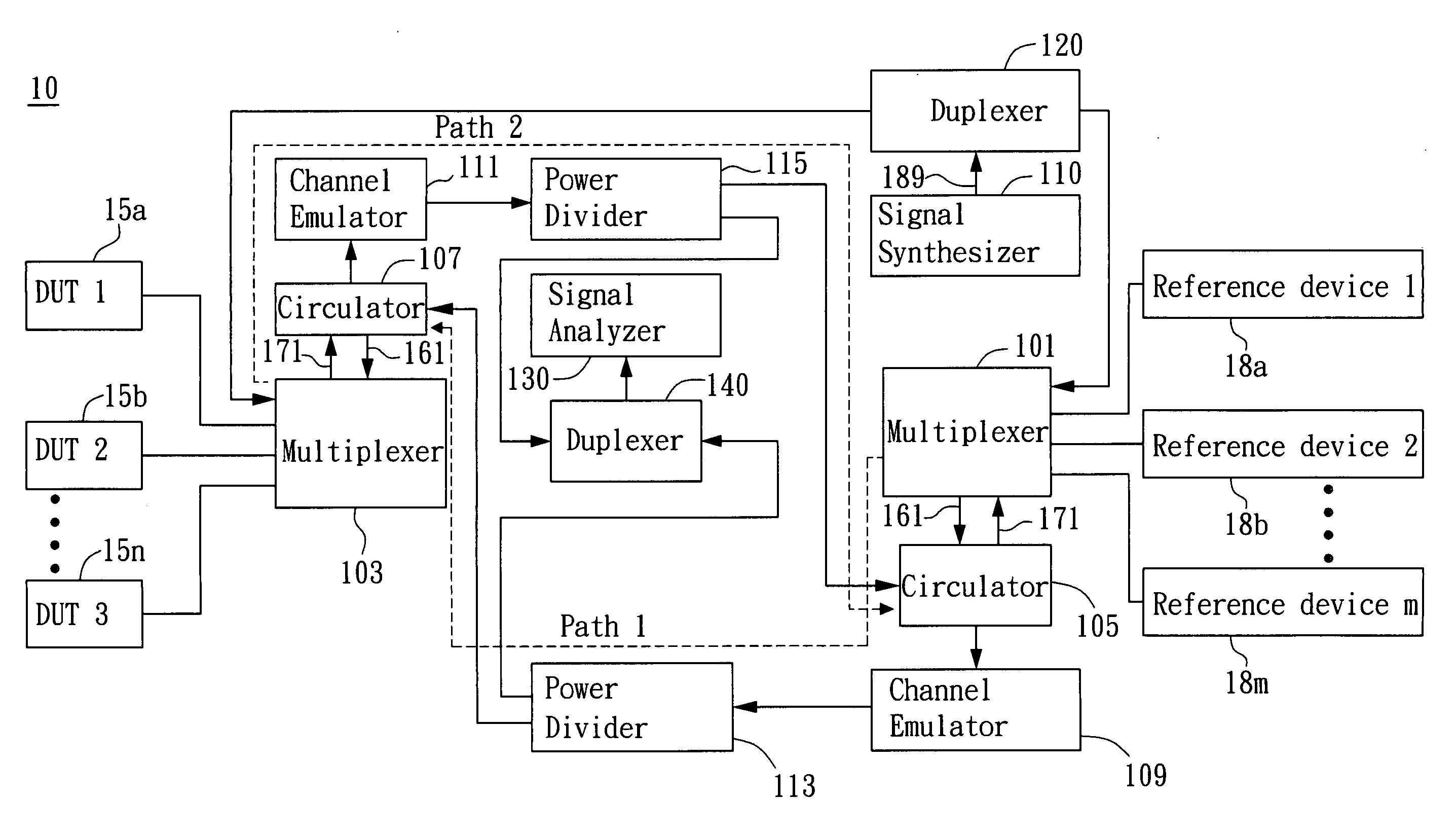
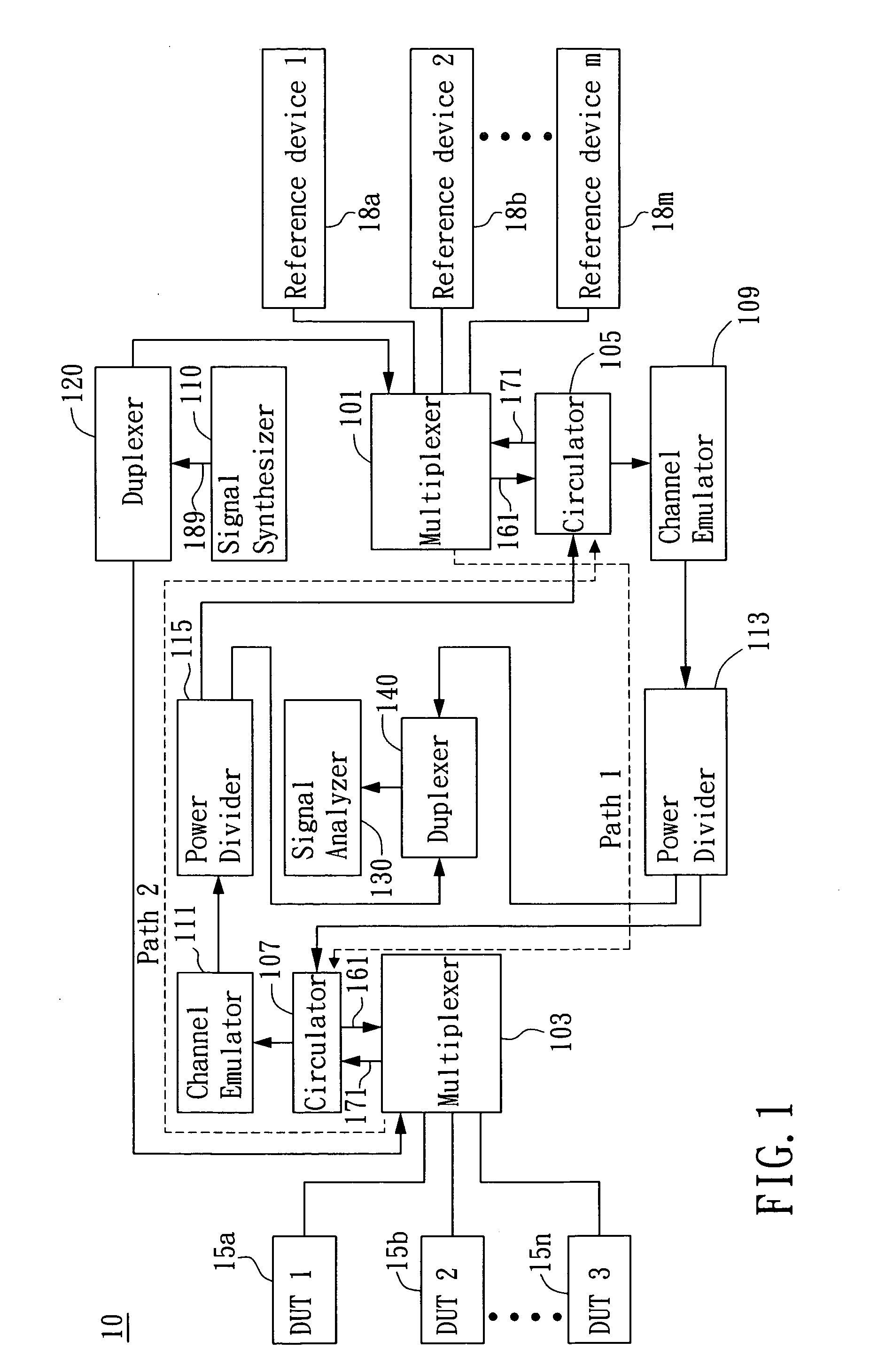
[0028] Please refer to FIG. 1, which is a schematic diagram depicting a signal testing system of the invention. The signal testing system 10 comprises two multiplexers 101, 103, two circulators 105, 107, two channel emulators 109, 111, two power dividers 113, 115, a signal analyzer 130, and a signal synthesizer 110. While using a plurality of reference devices 18a˜18m as transmitters (Tx), the signal test system 10 can provide a simulated wireless transmission path, i.e. the dotted arrow of path 1 shown in FIG. 1, enabling the signals outputted from the transmitters to be transmitted sequentially through the multiplexer 101, the circulator 105, the channel emulator 109, the power divider 113, the circulator 107, the multipl...


PUM


Abstract

A signal testing system is disclosed, which is capable of achieving a bi-directional wireless transmission measurement enabling mutual testing between device-under-tests and reference devices by configuring a symmetrical structure with circulators and multiplexers. Moreover, the signal testing system not only is capable of fetching signal out of a test path by the use of power dividers and then transmitting the fetched signal to a signal analyzer to be analyzed so as to enable the system to support multiple testing, but also is capable of generating a signal used for referencing by a signal synthesizer so as to enable the system to support numerous tests. In addition, both the signal analyzer and the signal synthesizer have a switch control integrated therein, which enables the signal analyzer to perform analysis on signals of different frequency bandwidth, and enables the signal synthesizer to generate signals of different frequency bandwidth as require.

Description

FIELD OF THE INVENTION [0001] The present invention relates to a signal testing system, and more particularly, to a signal testing system having an integrated, self-contained, flexible and automatic architecture for fitting itself in the manners (a) of making devices be under test or be of reference; (b) for testing in batch or in individual; (c) for testing in parallel or in sequential; (d) which supporting numerous tests; and (e) which supporting complicated test items. BACKGROUND OF THE INVENTION [0002] With rapid advance of wireless technology, wireless electronic devices are becoming essentials for our daily life. Among those, equipment enabling wireless connection like wireless networking card, base station, and so on, had facilitated our life ever further. In the process of manufacturing that wireless equipment, it is important to cooperate proper test measurements into the process since the production cost and quality might depend on a well-designed signal testing system per...

Claims


Application Information

Patent Timeline
Patent Type & Authority Applications(United States)
IPC IPC(8): H04Q7/20H04W24/06
CPCH04W24/06
Inventor LIU, I-RU
Owner ARCADYAN
Why Eureka
Try Eureka