Vehicle vision system with blind zone display and alert system

a technology of blind zone display and alert system, which is applied in the field of exterior rearview mirror system, can solve the problems of difficult determination by the driver of the host vehicle, and achieve the effect of enhancing cognitive awareness

Inactive Publication Date: 2018-05-17
MAGNA MIRRORS OF AMERICA INC
View PDF17 Cites 80 Cited by
  • Summary
  • Abstract
  • Description
  • Claims
  • Application Information

AI Technical Summary

Benefits of technology

[0005]The present invention provides a vision system for displaying video images of a side region or blind spot region at the side of the vehicle for viewing by the driver of the vehicle. Optionally, a video display screen may be disposed in the vehicle cabin and generally at or mounted at an inside portion of the vehicle door. Optionally, a video display screen may be disposed at a wide angle spotter mirror location (such as at an upper outboard corner region) of the reflective element of the exterior rearview mirror assembly mounted at the exterior side of the vehicle. The video display screen displays video images captured by the exterior viewing camera and provides a graphic overlay at the displayed images, with the graphic overlay extending perspectively along the side region of the vehicle with indications (such as short laterally extending portions or segments or different shadings or colors or the like) to show distance of objects or vehicles from the vehicle (such as both laterally from the vehicle and rearwardly of the vehicle). The displayed graphic overlay thus provides enhanced cognitive awareness for the driver in understanding the distance of the vehicles present in the camera's field of view.

Problems solved by technology

It is known to provide an object in a blind spot detection / LCA system for a vehicle that detects the presence of another vehicle or object in the lane next to the host vehicle, where it may be difficult for the driver of the host vehicle to determine whether or not there is another vehicle or object adjacent to the host vehicle.

Method used


Image

  • Vehicle vision system with blind zone display and alert system
  • Vehicle vision system with blind zone display and alert system
  • Vehicle vision system with blind zone display and alert system

Examples


Embodiment Construction

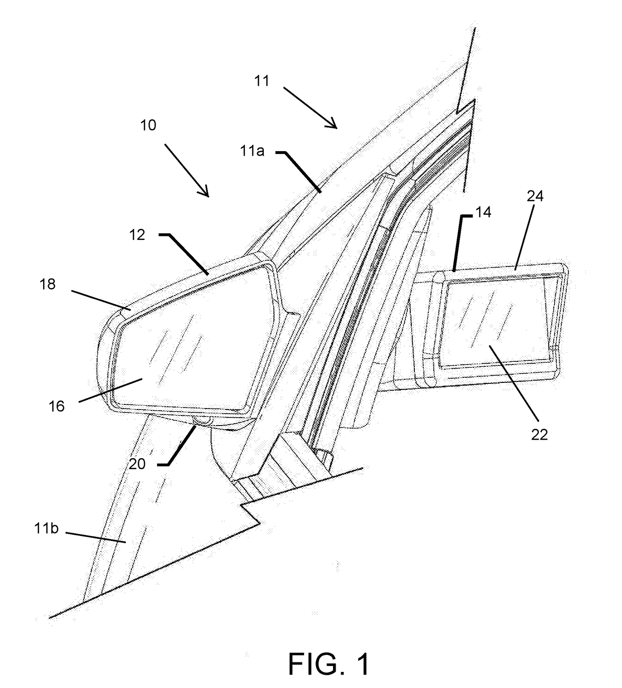
[0062]Referring now to the drawings and the illustrative embodiments depicted therein, an exterior rearview mirror system 10 for a vehicle 11 includes an exterior rearview mirror assembly 12 and an in-cabin display device or module 14 disposed at or mounted at the interior of the vehicle door 11 a or otherwise near to the exterior rearview mirror assembly 12 (FIG. 1). The exterior rearview mirror assembly 12 is mounted at the side 11 b of the host or subject or equipped vehicle 11 and includes a mirror reflective element 16 and a mirror shell or casing 18, and a camera or imaging sensor 20 that is disposed at the mirror casing 18 and has a generally rearwardly and sidewardly field of view at the side of the equipped vehicle.

[0063]In the illustrated embodiment, exterior rearview mirror assembly 12 may comprise a small or reduced size reflective element 16 that meets, but does not exceed or substantially exceed, the minimum size requirements (for example, the reflective element may ha...


PUM


Abstract

A vision system for a vehicle includes an exterior structure mounted at an exterior portion of a body side of the equipped vehicle, with an imaging sensor disposed at the exterior structure and having a field of view exterior and sideward and rearward of the vehicle. A video display screen is disposed in an interior cabin of the equipped vehicle and operable to display video images. Responsive to detection of another vehicle at or near the side of the equipped vehicle, said video display screen displays a graphic overlay at the display screen. The graphic overlay includes a semitransparent overlay having a longitudinally extending line segment that extends along a displayed body side portion of the equipped vehicle and a plurality of laterally extending line segments that extend laterally outwardly from the longitudinally extending line segment at spaced apart intervals along the longitudinally extending line segment.

Description

CROSS REFERENCE TO RELATED APPLICATIONS[0001]The present application claims the filing benefits of U.S. provisional applications, Ser. No. 62 / 269,350, filed Dec. 18, 2015; Ser. No. 62 / 222,269, filed Sep. 23, 2015, and Ser. No. 62 / 157,605, filed May 6, 2015, which are hereby incorporated herein by reference in their entireties.FIELD OF THE INVENTION[0002]The present invention relates to exterior rearview mirror systems and, more particularly, to an exterior rearview mirror system having a blind spot / object detection and display system at the exterior rearview mirror assembly and door of the vehicle.BACKGROUND OF THE INVENTION[0003]It is known to provide an object in a blind spot detection / LCA system for a vehicle that detects the presence of another vehicle or object in the lane next to the host vehicle, where it may be difficult for the driver of the host vehicle to determine whether or not there is another vehicle or object adjacent to the host vehicle. Such an object in a blind sp...

Claims


Application Information

Patent Timeline
Patent Type & Authority Applications(United States)
IPC IPC(8): B60R1/06G06T11/60G06K9/00G08G1/16
CPCB60R1/06G06T11/60G06K9/00805G08G1/167B60R2300/8026B60R2300/8046H04N7/188G06V20/58
Inventor PETERSON, KENNETH C.HUIZEN, GREGORY A.LYNAM, NIALL R.
Owner MAGNA MIRRORS OF AMERICA INC
Why Eureka
Try Eureka