Box shaped bilge keel

a box-shaped bilge keel technology, applied in the field of floating vessels, can solve the problems of reducing the heave and pitch motion of the plate, the plate cannot provide only limited stability to the floating vessel, and the plate does not have any impact on the reduction of the heave and pitch motion, so as to achieve more damping and reduce the pitch motion considerably

Inactive Publication Date: 2018-05-17
PRISERVE ENG INC
View PDF4 Cites 1 Cited by
  • Summary
  • Abstract
  • Description
  • Claims
  • Application Information

AI Technical Summary

Benefits of technology

[0016]The box shaped bilge keel offers a number of advantages. The box shaped bilge keel generates more damping for roll and heave motions and reduces pitch motion considerably as compared to the traditional bilge keels.

Problems solved by technology

The aforesaid documents and other solutions may aim to provide bilge keels for floating vessels, however they still suffer from a number of deficiencies.
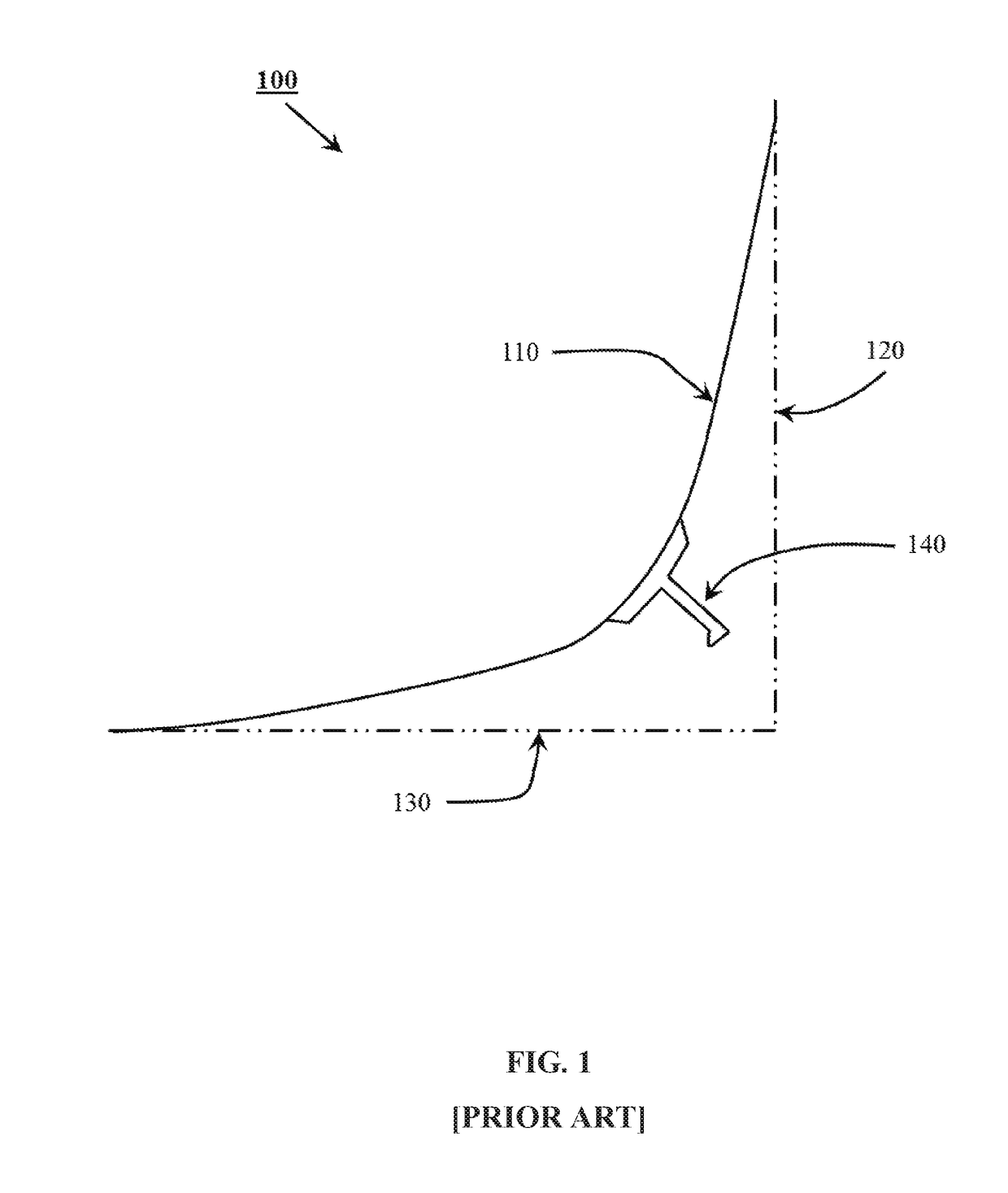
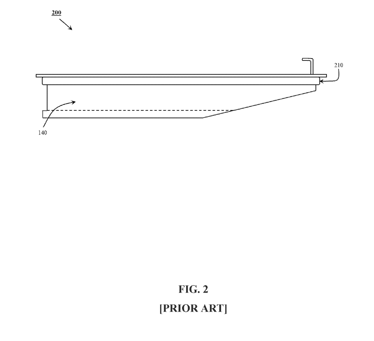
First, most of the bilge keels are made of plates, while plates can provide only limited stability to the floating vessel.
Further, the plates do not have any impact on reducing heave and pitch motions.
Moreover, the sponson and the wing keel arrangement is rather complex and comparatively expensive to implement.

Method used


Image

  • Box shaped bilge keel
  • Box shaped bilge keel
  • Box shaped bilge keel

Examples


Embodiment Construction

[0025]Detailed embodiments of the present disclosure are described herein; however, it is to be understood that disclosed embodiments are merely exemplary of the present disclosure, which may be embodied in various alternative forms. Specific process details disclosed herein are not to be interpreted as limiting, but merely as a representative basis for teaching one skilled in the art to variously employ the present disclosure in any appropriate process.

[0026]The terms used herein are for the purpose of describing exemplary embodiments only and are not intended to be limiting. As used herein, the singular forms “a,”“an,” and “the” are intended to include the plural forms as well, unless the context clearly indicates otherwise. It will be further understood that the terms “comprises” or “comprising,” when used in this specification, do not preclude the presence or addition of one or more components, steps, operations, and / or elements other than a mentioned component, step, operation,...


PUM


Abstract

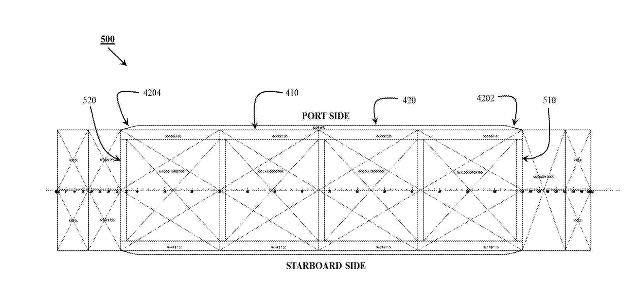
A box shaped bilge keel comprises a convex polygonal shaped cross-section. Further, the box shaped bilge keel extends along a pre-determined length of a hull of a floating vessel. Also, the box shaped bilge keel is providing additional width to the hull at the bottom of the floating vessel.

Description

FIELD OF THE INVENTION[0001]Embodiments of the present invention relate to floating vessels and more particularly to a box shaped bilge keel for the floating vessels.BACKGROUND ART[0002]Dynamic motions for floating vessels such as FSRUs (Floating Storage Regasification Units) are important design considerations during initial stages of design. Dynamic motions such as heave, roll and pitch motions introduce additional loads on hull structure and operational restrictions during the loading / offloading of cargo. Also, higher dynamic motions affect crew operability and comfort. Bilge keels are usually employed at sides of the floating vessels to reduce tendency of the floating vessels to roll.[0003]Generally, bilge keels are in the form of a ‘strake’ or ‘plate’ on the sides of the floating vessels. Some of the bilge keel designs have been discussed below:[0004]U.S. Pat. No. 6,176,191B1 discloses bilge keels for an FPSO type petroleum production system. The bilge keels have two lines of p...

Claims


Application Information

Patent Timeline
Patent Type & Authority Applications(United States)
IPC IPC(8): B63B3/44
CPCB63B3/44Y02T70/10
Inventor KIM, DANIEL DOOGYOONPRASAD, SAUMENMOYYETI, SURESH KUMAR
Owner PRISERVE ENG INC
Why Eureka
Try Eureka