Semi-submersible floating structure for vortex-induced motion performance

a technology of vortex-induced motion and semi-submerged floating structure, which is applied in the direction of water supply installation, special-purpose vessels, vessel construction, etc., can solve the problems of counter-intuitive creation of interfering vortex flows, and achieve even smaller vim, reduce the effective vim excitation length of the column, and reduce the effect of vim

Active Publication Date: 2014-06-24
TECH FRANCE SA
View PDF36 Cites 2 Cited by
  • Summary
  • Abstract
  • Description
  • Claims
  • Application Information

AI Technical Summary

Benefits of technology

[0017]The disclosure provides a semi-submersible offshore platform with columns having an enlarged base on the bottom of each column with pontoons coupled between the columns. The enlarged base forms a column bottom portion with horizontal dimension extending horizontally outward from the column perimeter. The enlarged base can extend outward from the column at least 10% of a width of a column coupled to the at least one column base. In some embodiments, the enlarged base can extend in all directions from the column, herein “symmetrically”, and in other embodiments the enlarged base can extend in less than all directions from the column, herein “asymmetrically”. The enlarged base can be one single volume or multiple unconnected volumes. The enlarged base changes flow pattern around the base and column and breaks the coherence of vortex shedding. One example of such an enlarged base is a 45 degree, rotated square that is concentric with the column. The inboard corners of this rotated square base can be trimmed to match the pontoon width. The outward corners of this square base can also be trimmed for construction convenience, or other design considerations. Although the base height can vary relative to the pontoon height from lower to higher, the enlarged base is generally at least as high as the pontoon height and in some embodiments higher. When the enlarged base is higher than the pontoon, a top of the base is at an elevation between a top of the pontoon and a surface of water in which the platform floats. In at least one embodiment, the base height can be between 20 to 60% of the draft of the platform. In some embodiments, the pontoon volume can be reduced inversely proportional to the base enlargement to have comparable total buoyancy. The base itself can be further increased in size near the bottom of the base to accommodate other requirements, such as buoyancy at quayside.
[0018]It is believed that the enlarged base breaks the coherence of vortex shedding along the column length and therefore lowers the VIM. it is believed that the vortex shedding coherence along the column length is interrupted to some degree and the effective VIM excitation length of the column is reduced. It appears that the synchronization of the vortex shedding between columns is interrupted to some degree as well. The VIM is expected to be less than a similar semi submersible platform with constant cross-section columns with a deep draft. It is believed that the base and its structural interruptions in the column profile form interfering vortex flows that interrupt the overall vortex flow. This creation of interfering vortex flows is counterintuitive to typical design efforts in the industry that generally seek to limit vortex creation and seek to provide smooth flows around an offshore structure. In addition, the higher than conventional pontoons make VIM even smaller by providing more damping.
[0020]The disclosure provides a method of improving vortex-induced motion of a semi-submersible floating offshore platform, the platform having a plurality of columns coupled to a deck and spaced apart from each other, the columns having a column height measured from a bottom of the columns to the deck, at least two column bases coupled to at least two columns, the column bases having a base height, and at least two pontoons coupled to at least one of the column, column bases, or a combination thereof, the pontoons having a pontoon height, wherein the offshore structure has a draft height for floating in water, and at least one of the column bases has a base height of 20% to 60% of the draft height and has an extension width that is at least 10% of a width of a column coupled to the at least one column base, comprising: allowing water to flow by the offshore structure; and breaking a coherence in vortex shedding around the offshore structure by creating interfering vortex currents around at least one of the columns and the column base coupled to the column as water flows by the column and column base.

Problems solved by technology

It is believed that the base and its structural interruptions in the column profile form interfering vortex flows that interrupt the overall vortex flow.
This creation of interfering vortex flows is counterintuitive to typical design efforts in the industry that generally seek to limit vortex creation and seek to provide smooth flows around an offshore structure.

Method used


Image

  • Semi-submersible floating structure for vortex-induced motion performance
  • Semi-submersible floating structure for vortex-induced motion performance
  • Semi-submersible floating structure for vortex-induced motion performance

Examples


example

[0058]FIG. 6 is a Vortex-Induced-Motion (VIM) graph of various tested configurations for contrasting the behavior and the resulting VIM around the offshore platform 5 between a conventional semi-submersible floating offshore platform design and various embodiments of the new design described herein. FIG. 6 illustrates a representative chart from such VIM test results.

[0059]The tests were performed in a still water towing tank with the model towed by a carriage to simulate a uniform and constant current. One spring was attached to each corner of the model, the other end of the spring was fixed to the carriage. The six (6) degrees of freedom motions of the model were measured by an optical tracking system, and the tension of each spring was measured by an inline load cell. The speed of the carriage was adjustable and the entire velocity range of interest was covered by multiple tows.

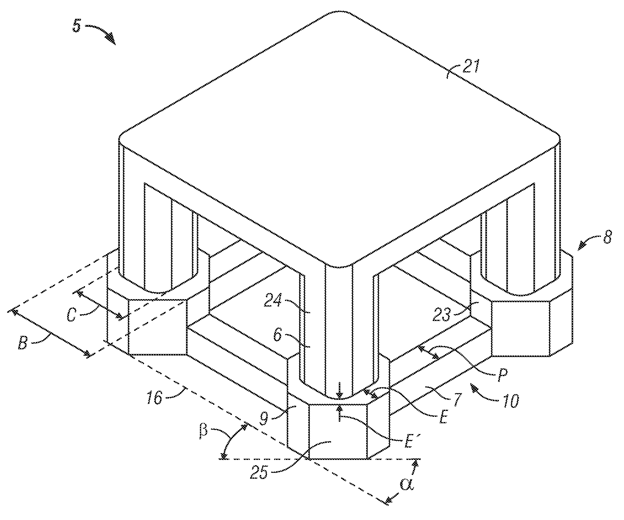
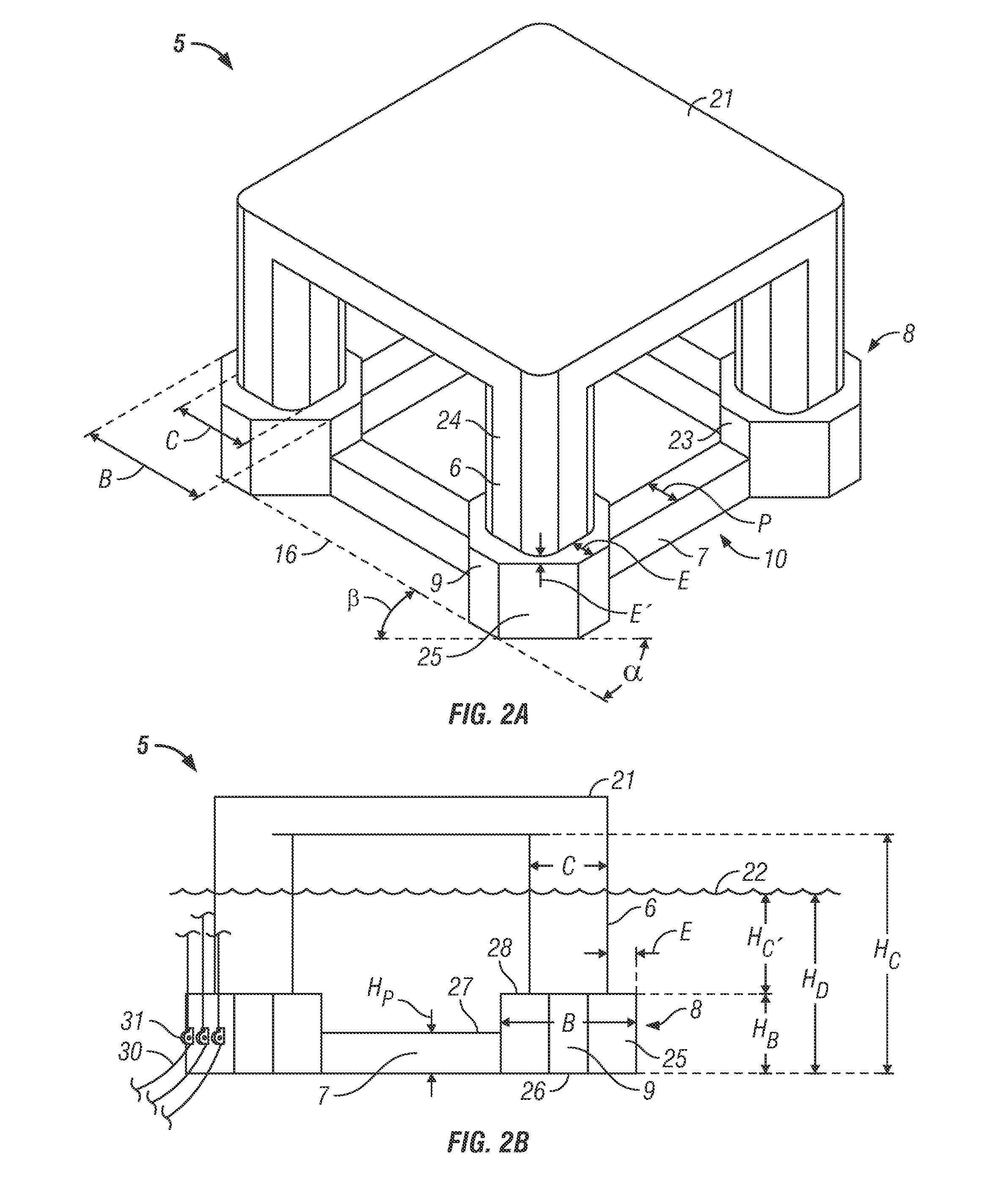
[0060]Cases 1, 2, and 3 are all of type as exemplified in FIG. 3A. Case 1 includes a column having an a...


PUM


Abstract

The disclosure provides a semi-submersible offshore platform with columns having an enlarged base on the bottom of each column with pontoons coupled between the columns. The enlarged column base can be at least as high as a height of the pontoon and on at least embodiment can be about 50% of the draft of the platform. The enlarged base can change a current flow shape around the base and columns for lower VIM. An outside corner of the base can be trimmed at an angle. Alternatively, the lower portions of the columns can be extended horizontally outward to form an effectively enlarged base having similar characteristics. In some embodiments, the pontoon volume can be reduced inversely proportional to the base enlargement to have comparable total buoyancy.

Description

CROSS REFERENCE TO RELATED APPLICATIONS[0001]This application claims the benefit of U.S. Provisional Application No. 61 / 411,676, filed Nov. 9, 2010 and incorporated herein by reference.STATEMENT REGARDING FEDERALLY SPONSORED RESEARCH OR DEVELOPMENT[0002]Not applicable.REFERENCE TO APPENDIX[0003]Not applicable.BACKGROUND OF THE INVENTION[0004]1. Field of the Invention[0005]The disclosure relates to a system and method for a deep draft semi-submersible floating structure for drilling and production. More particularly, the disclosure relates to a system and method for a semi-submersible floating structure to minimize vortex-induced motion.[0006]2. Description of the Related Art[0007]Most conventional semi-submersible offshore platforms for offshore drilling and production comprise a hull that has sufficient buoyancy to support a work platform above the water surface. The hull typically includes at least two horizontal pontoons that support at least three vertical columns which support ...

Claims


Application Information

Patent Timeline
Patent Type & Authority Patents(United States)
IPC IPC(8): B63B35/44
CPCB63B2021/003B63B21/00B63B35/44B63B35/4413B63B1/107Y10T137/0318B63B2001/128B63B2039/067
Inventor XU, QI
Owner TECH FRANCE SA
Why Eureka
Try Eureka