
Composite plate and armor having at least one of the composite plates

a composite plate and composite plate technology, applied in the field of composite plate and armor having the composite plate, can solve the problems of significant decrease in the energy and deflection of the projectile, decrease in the penetration capacity of the projectile, etc., and achieve the effect of simplifying the assembly of the first layer, reducing the kinetic energy of the projectile, and strengthening the armor

Inactive Publication Date: 2012-06-14
FICHT FAHRZEUG MARINETECHN
View PDF2 Cites 8 Cited by
  • Summary
  • Abstract
  • Description
  • Claims
  • Application Information

AI Technical Summary

Benefits of technology

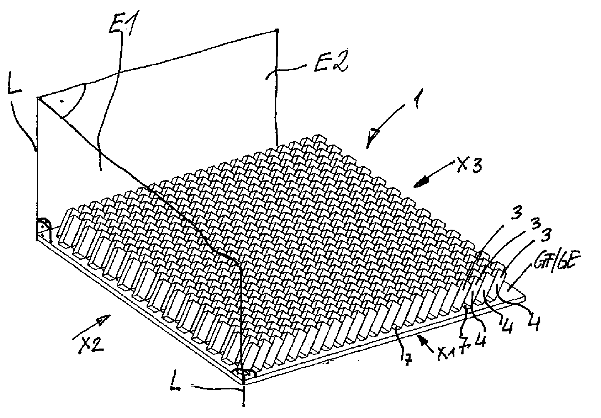
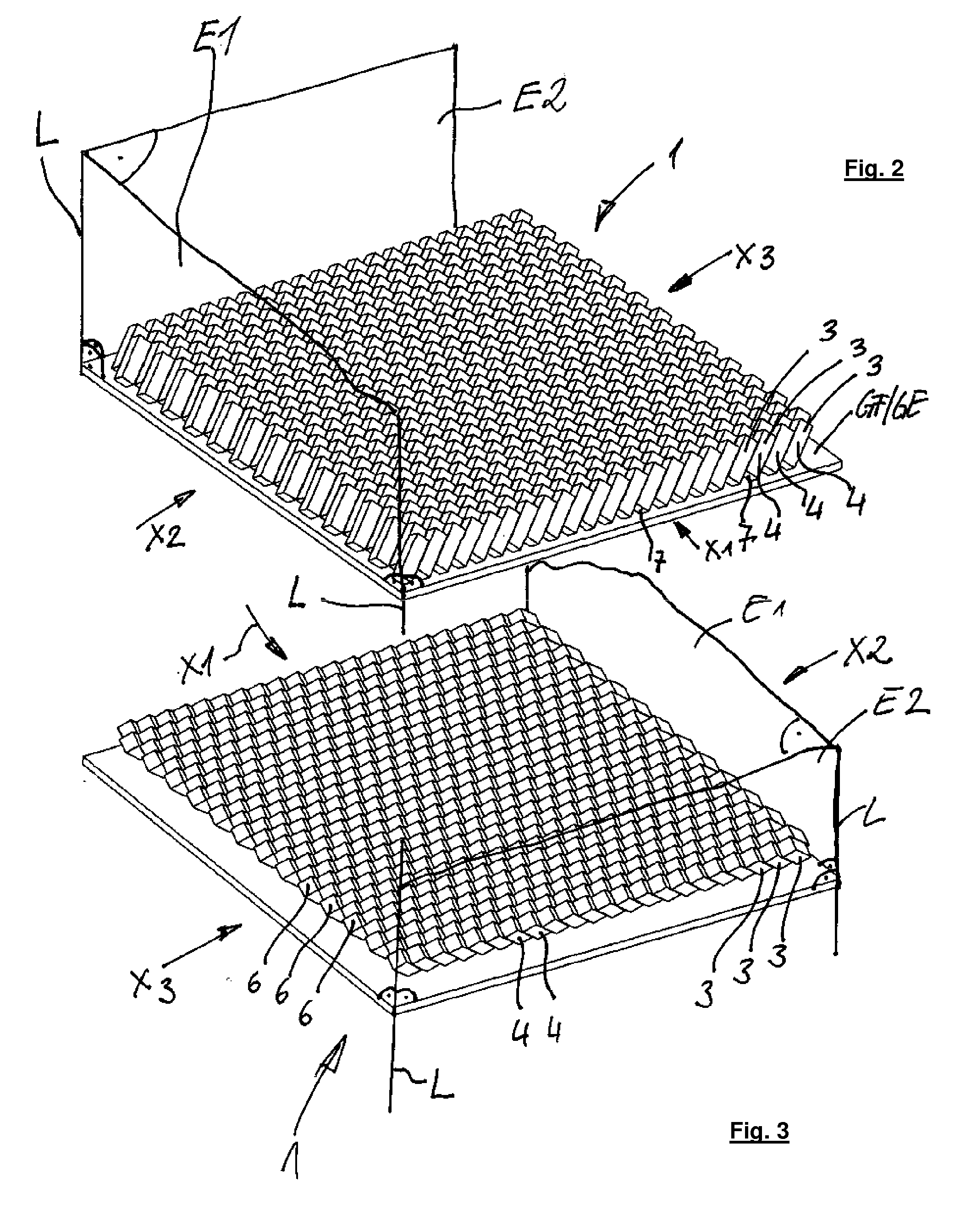
[0012]The invention is also based on the realization that adjacent bars are placed against one another without gaps at least partially by means of side surfaces or edges that face each other and the longitudinal axes of the bars are arranged in an inclined fashion enclosing angles α and β relative to a perpendicular L on a surface, in particular a plane, of the composite plate in at least two different planes E1 and E2 that are orthogonal to each other. Firstly, such a composite plate offers the possibility, for example, of constructing such a composite plate out of molded components that are very simple geometrically, e.g. blocks or cubes, that can also be inexpensively obtained in the form of ceramic components. For example, in order to construct a composite plate according to the invention, such bars can be obtained by being sawn off from ceramic bars, for example bars with a square cross-section. All of the bars are preferably embodied identically and, through the double-inclined positioning at the angles α and β, yield a composite plate that has only inclined surfaces facing the shelling side, which function as deflecting surfaces for an impacting projectile. Lateral forces are thus necessarily exerted on the impacting projectile. This results in a significant decrease in energy and a deflection of the projectile, possibly even resulting in the destruction of the hardened core of the projectile and consequently a decrease in its penetration capacity.
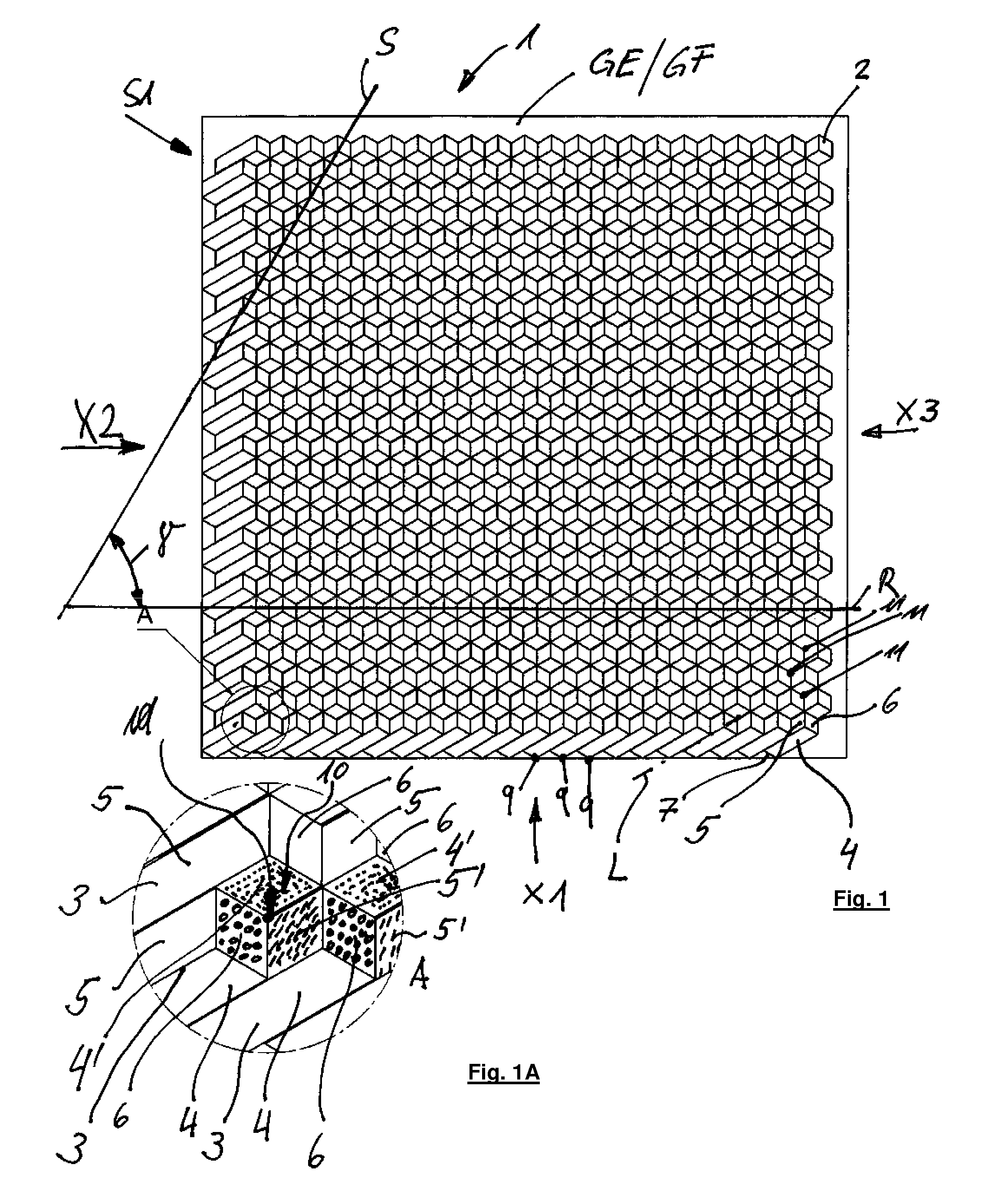
[0016]For reasons of symmetry and the associated uniform distribution of forces arising from impacting projectiles, it is advisable for the angles α and β to be selected as a function of the size of the end surfaces of the bars so that the surfaces delimiting the recess, i.e. the end surface of the first bar and the two subregions of the side surfaces of the other bars are of identical size in terms of area. This makes it possible to accommodate deflecting components in the form of balls so that the deflecting components can rest against all three of the surfaces constituting the recess and in addition, with a suitable selection of the size of the balls, the balls can easily touch all of the adjacent balls.
[0022]One way to construct armor is to place a plurality of flat composite plates adjacent to one another and, between adjacent flat composite plates, to provide an interstitial separating layer preferably composed of steel, a material that is more elastic and provides more damping than ceramic. As a result of this, a crack that forms within a composite plate due to a shelling of the composite plate cannot spread to adjacent composite plates, thus preventing a weakening of the latter.
[0025]In order to adapt to increased armor requirements, it has turned out to be useful to associate the composite plate with an additional layer of double-inclined bars and to place the second layer of double-inclined bars against the first layer of double-inclined bars in such a way that the individual bars of the two layers are aligned with one another in their longitudinal direction. This makes it possible to reinforce the armor in modular fashion by simply placing two structurally identical composite plates against each other.
[0026]Another possibility for combining two structurally identical layers of double-inclined bars is to place the second layer against the first layer so as to produce a composite in the form of a herringbone pattern when viewed from the side. This makes it possible for shock waves and compressive stresses caused by the impact of a projectile to be successfully deflected again in another direction and therefore further dissipated so as to thus further and more significantly reduce the kinetic energy of the projectile.
[0027]To simplify the assembly of a first layer composed of double-inclined bars, it has also turned out to be useful for a first row of the bars constituting the first layer to be embodied in the form of a one-piece molded component similar to a jagged plate, with the plane of the jagged plate in the composite inclined relative to the plane E1 or E2. This significantly reduces the number of molded components to be arranged. Conversely, it is necessary to accept a slightly increased manufacturing cost of the jagged molded plates.

Problems solved by technology

This results in a significant decrease in energy and a deflection of the projectile, possibly even resulting in the destruction of the hardened core of the projectile and consequently a decrease in its penetration capacity.

Method used


Image

  • Composite plate and armor having at least one of the composite plates
  • Composite plate and armor having at least one of the composite plates
  • Composite plate and armor having at least one of the composite plates

Examples


Embodiment Construction

[0091]In a first embodiment (FIGS. 1 through 6), a composite plate 1 according to the invention has at least one first layer S1 for deflecting a projectile 12; the layer S1 is composed of a multitude of ceramic molded components 2 situated adjacent to one another in rows R and columns S.

[0092]In a top view of the composite plate 1 according to the invention shown in FIG. 1, the columns S enclose an angle α with the rows R. The composite plate 1 according to the invention is essentially a flat structure. For the sake of clarity, in FIG. 1 and in various figures below, a basal plane GE is indicated that is essentially intended to illustrate the three-dimensional space of the composite plate 1. The basal plane GE should not be viewed as another layer of the composite plate 1.

[0093]It is naturally also possible to construct the composite plate using basal surfaces other than a basal plane, e.g. arched and / or bossed basal surfaces.

[0094]According to the invention, the ceramic molded comp...


PUM


Abstract

The invention relates to a composite plate having at least one layer for deflecting a projectile, said layer being composed of a multitude of molded components arranged adjacent to one another; the molded components are embodied in the form of bars that have side surfaces and end surfaces and have the capacity to be arranged in series with one another without gaps; adjacent bars are arranged adjacent to one another without gaps at least partially by means of side surfaces or edges that face each other and the longitudinal axes of the bars are arranged in an inclined fashion enclosing angles α and β relative to a perpendicular (L) on a surface of the composite plate in at least two different planes E1 and E2 that are perpendicular to each other.

Description

FIELD OF THE INVENTION[0001]The invention relates to a composite plate and an armor having the composite plate.BACKGROUND OF THE INVENTION[0002]DE 3507216 A1 has disclosed a composite plate having at least one steel layer and one ceramic layer, one steel layer having recesses in which appropriately shaped ceramic molded components are situated. The ceramic molded components are embodied of one piece and are each composed of a truncated cone and a hemisphere, with the truncated cones and hemispheres respectively embedded in steel plates. It has turned out that with the impact of a high velocity hardened-core kinetic energy penetrator, steel armors, due to the occurrence of high local pressures, behave similarly to fluids and therefore do not offer effective protection from shelling with this type of ammunition. When subjected to shelling, the ceramic molded components accommodated between steel plates consequently likewise cannot be sufficiently secured in position so that the armor ...

Claims


Application Information

Patent Timeline
Patent Type & Authority Applications(United States)
IPC IPC(8): F41H5/04F41H5/02
CPCF41H5/0492
Inventor FICHT, REINHOLDSTEINBEI ER, TOBIAS
Owner FICHT FAHRZEUG MARINETECHN
Learn More