
DNA structured linear actuator

a linear actuator and dna technology, applied in the field of linear actuators, can solve the problems of non-linear response in length change and torque, limited change in limited change in the overall length of the actuator, so as to increase the gear ratio, reduce the overall length of the structure, and be lightweight.

Active Publication Date: 2018-05-17
RGT UNIV OF CALIFORNIA
View PDF0 Cites 1 Cited by
  • Summary
  • Abstract
  • Description
  • Claims
  • Application Information

AI Technical Summary

Benefits of technology

The present invention is a linear actuator that has a unique structure similar to DNA, which can provide advantages in cost, scale, speed, and efficiency. It is a compliant actuator, which is beneficial for interactive robotics. The actuator has a ladder-like structure that twists to generate linear motion, which is fast and efficient. The actuator is also scalable in size and can handle various loads and geometries. Overall, the DNA-structured linear actuator is a strong performer in all performance categories (cost, scale, speed, and efficiency).

Problems solved by technology

While these are all valid methods of generating linear motion, each of these methods has its own issues, resulting in niche applications for each.
The main issues with linear actuation methods are cost, scale, speed, and efficiency.
The main disadvantages of TSAs are their non-linear response in length change and torque, and their limited change in overall length of the actuator.
Screw based actuators tend to be heavy, require large amounts of space, are rigid, slow and are generally expensive.

Method used


Image

  • DNA structured linear actuator
  • DNA structured linear actuator
  • DNA structured linear actuator

Examples


Embodiment Construction

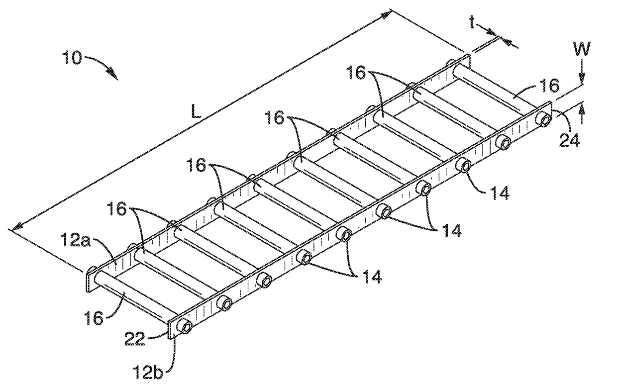
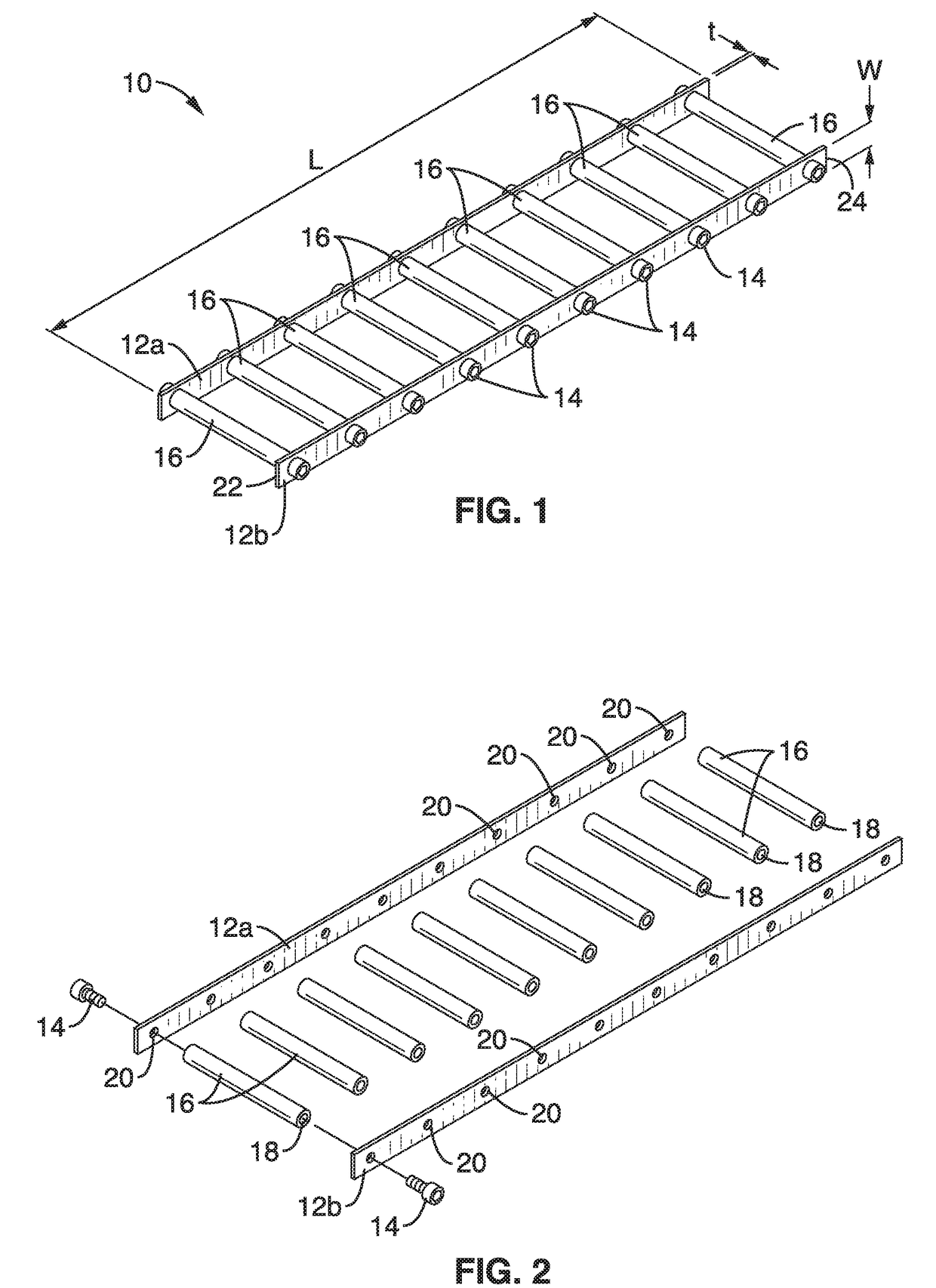
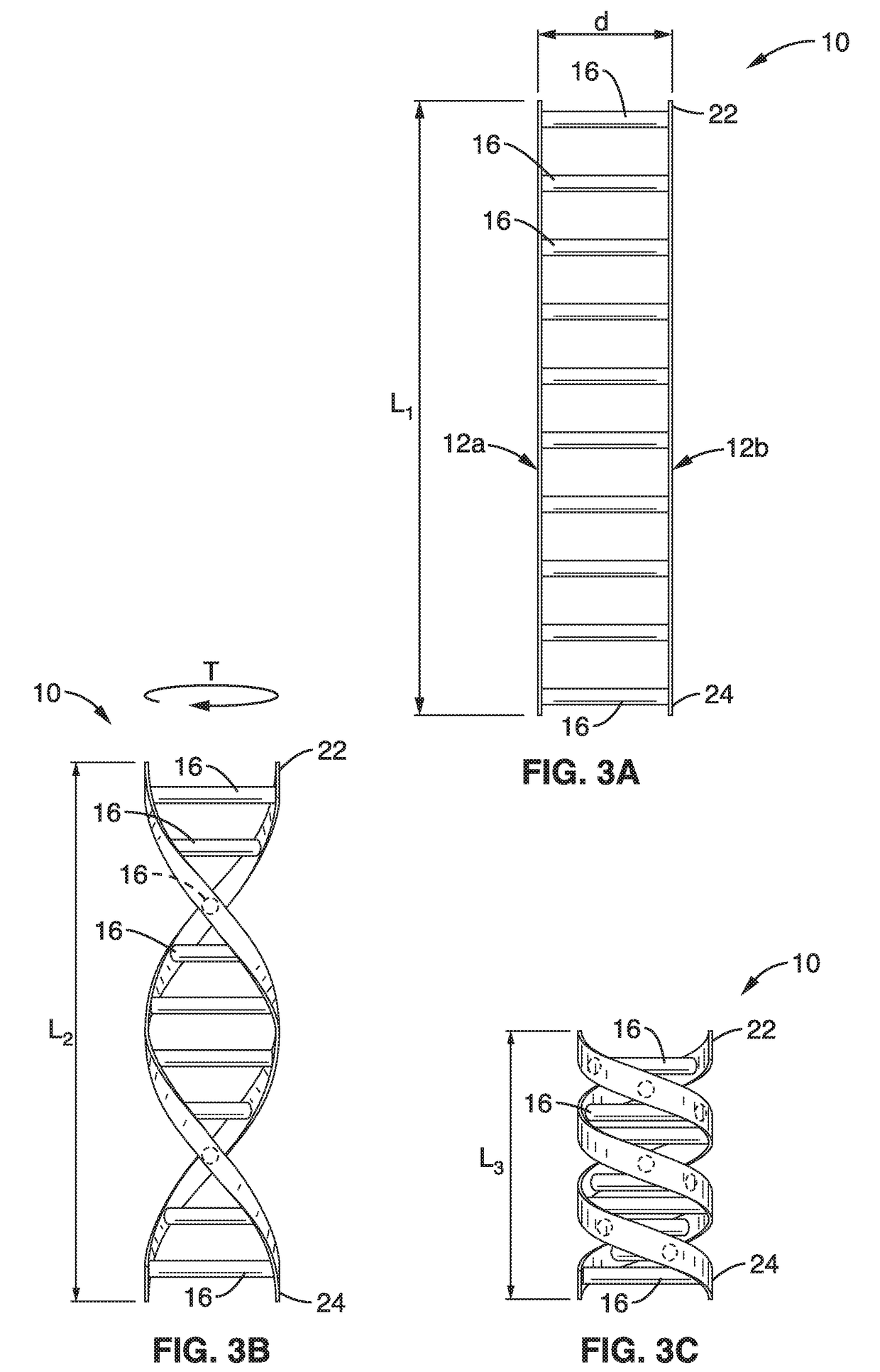
[0022]FIG. 1 shows a schematic perspective view of the DNA-structured linear actuator 10 of the present description. FIG. 2 is an exploded assembly view of the DNA-structured linear actuator 10. The linear actuator 10 comprises a ladder-like structure that when twisted along its length resembles a strand of DNA. The actuator 10 comprises a pair of elongate, flexible planar rails (12a, 12b) that are spaced apart by distance d via a plurality of cylindrical rungs 16.

[0023]The rungs 16 are attached to the rails 12a, 12b via a plurality of fasteners 14 at spaced-apart locations on the rails 12a, 12b. Each of the rungs 16 has a first end coupled to the first rail 12a and a second end coupled to the second rail 12b such that the first and second rails 12a, 12b are spaced apart parallel to each other to form a ladder-like structure having a first rail end 22 and a second rail end 24 with a rail length L established at points between rail ends 22, 24. The rails 12a, 12b shown in FIG. 1 and ...


PUM


Abstract

A DNA-structured linear actuator comprised of a ladder-like structure that twists to generate linear motion. In its base state, the DNA structured linear actuator best resembles a rope ladder. When this ladder is twisted, it takes on the appearance of a DNA double-helix structure. By application of a torsional force on one end, the ladder-like structure extends or contracts to allow linear translation of one end of the structure.

Description

CROSS-REFERENCE TO RELATED APPLICATIONS[0001]This application is a 35 U.S.C. §111(a) continuation of PCT international application number PCT / US2016 / 032899 filed on May 17, 2016, incorporated herein by reference in its entirety, which claims priority to, and the benefit of, U.S. provisional patent application Ser. No. 62 / 163,462 filed on May 19, 2015, incorporated herein by reference in its entirety. Priority is claimed to each of the foregoing applications.[0002]The above-referenced PCT international application was published as PCT International Publication No. WO 2016 / 187211 on Nov. 24, 2016, which publication is incorporated herein by reference in its entirety.STATEMENT REGARDING FEDERALLY SPONSORED RESEARCH OR DEVELOPMENT[0003]Not ApplicableINCORPORATION-BY-REFERENCE OF COMPUTER PROGRAM APPENDIX[0004]Not ApplicableNOTICE OF MATERIAL SUBJECT TO COPYRIGHT PROTECTION[0005]A portion of the material in this patent document is subject to copyright protection under the copyright laws ...

Claims


Application Information

Patent Timeline
Patent Type & Authority Applications(United States)
IPC IPC(8): H02N2/04B25J9/10B25J17/02
CPCH02N2/04B25J9/10B25J17/0208H02K29/03H02K1/143H02K1/146H02K2213/03F16H19/0654
Inventor AGOGINO, ALICEZAMPAGLIONE, KYLECHEN, LEE-HUANGSABELHAUS, ANDREW P.
Owner RGT UNIV OF CALIFORNIA
Learn More