Pulmonary Embolism Apparatus

a pulmonary embolism and pulmonary artery technology, applied in the field of pulmonary embolism apparatus, can solve the problems of increasing the risk of internal bleeding, and no convenient way to monitor right-side heart strain and pulmonary artery pressure in real time, so as to improve the ability to monitor pulmonary artery pressure, improve the risk of internal bleeding, and improve the effect of clinical decision-making

Active Publication Date: 2018-05-24
SANFORD HEALTH
View PDF10 Cites 0 Cited by
  • Summary
  • Abstract
  • Description
  • Claims
  • Application Information

AI Technical Summary

Benefits of technology

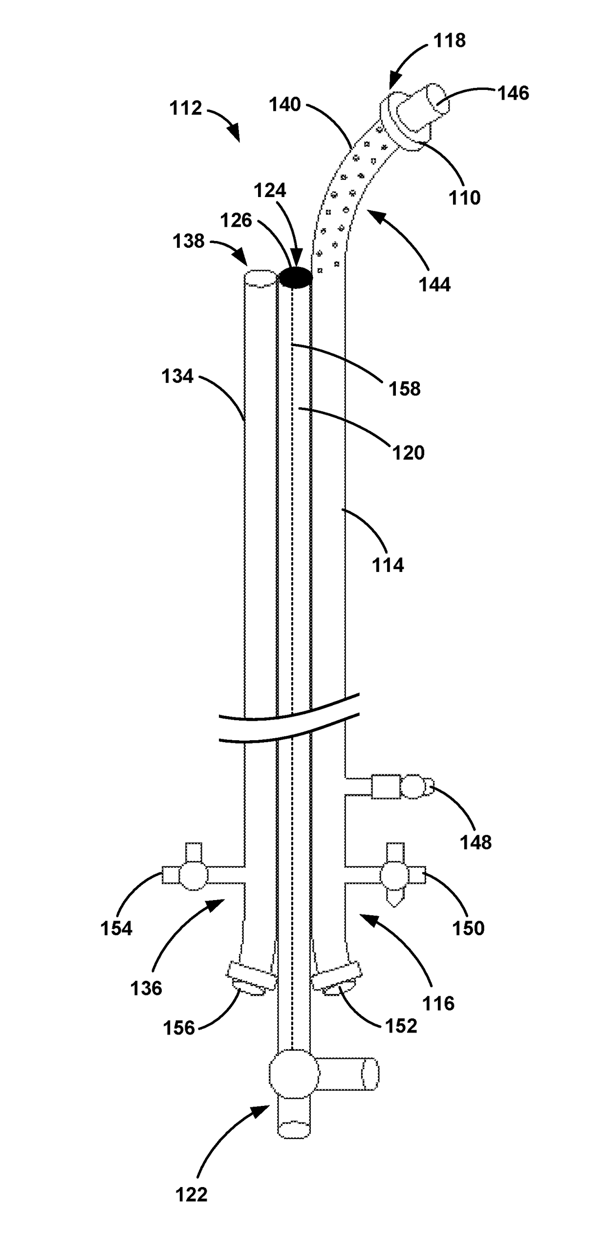
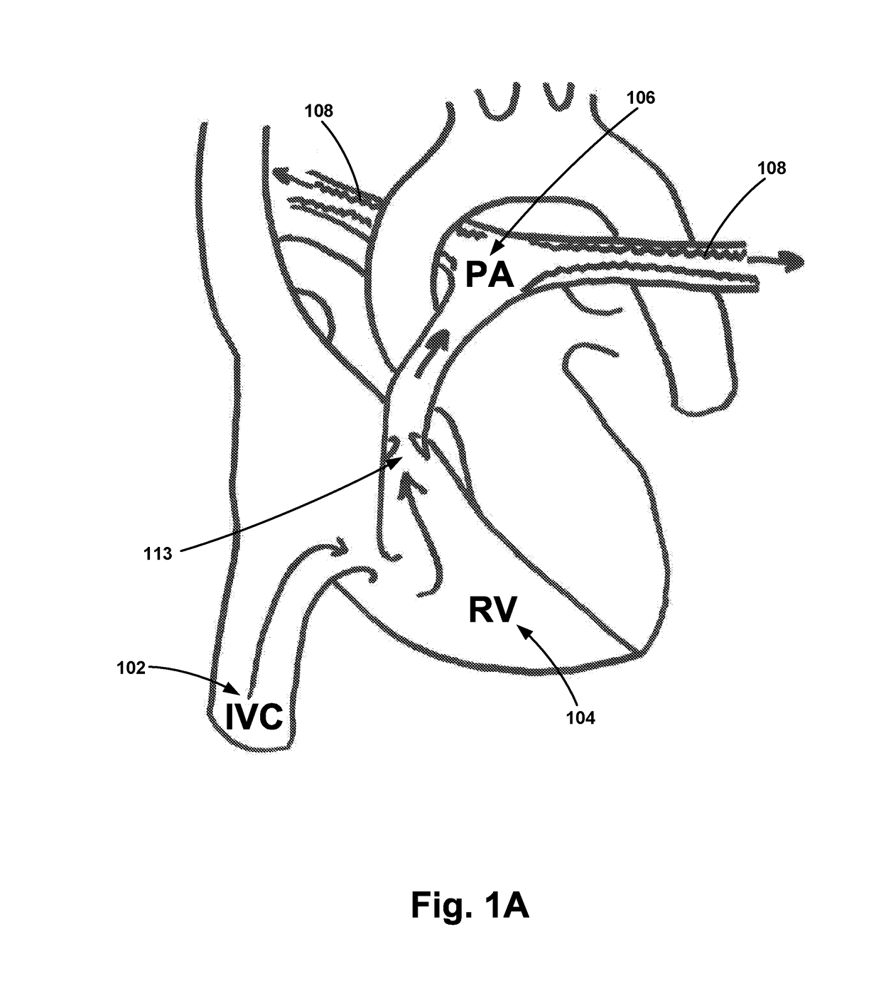
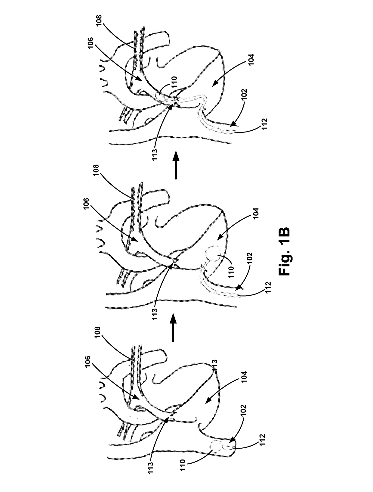
[0008]The present invention is directed to a device that improves the ability to monitor pulmonary artery pressures to aid in clinical decision making. For example, there is currently no convenient way to monitor right-side heart strain and pulmonary artery pressures in real time, and current treatment methods typically require long treatment durations to ensure that an embolism has cleared. The longer patients are exposed to medications or treatment solutions that dissolve clots, the greater the risk of internal bleeding. Internal bleeding can be devastating in situations such as intra-cranial hemorrhage. Therefore, determining when the embolism has been sufficiently treated would be advantageous to shorten delivery time for the treatment solution. The apparatus described herein may be used for improving the delivery of treatment solutions to the pulmonary arteries for treatment of pulmonary embolisms. Further, in one embodiment, the apparatus may include a mechanism to detect when healthy blood flow through the pulmonary arteries is reestablished, thereby indicating the treatment is completed.

Problems solved by technology

For example, there is currently no convenient way to monitor right-side heart strain and pulmonary artery pressures in real time, and current treatment methods typically require long treatment durations to ensure that an embolism has cleared.
The longer patients are exposed to medications or treatment solutions that dissolve clots, the greater the risk of internal bleeding.
Internal bleeding can be devastating in situations such as intra-cranial hemorrhage.

Method used


Image

  • Pulmonary Embolism Apparatus
  • Pulmonary Embolism Apparatus
  • Pulmonary Embolism Apparatus

Examples


Embodiment Construction

[0024]Exemplary devices and methods are described herein. It should be understood that the word “exemplary” is used herein to mean “serving as an example, instance, or illustration.” Any embodiment or feature described herein as “exemplary” is not necessarily to be construed as preferred or advantageous over other embodiments or features. The exemplary embodiments described herein are not meant to be limiting. It will be readily understood that certain aspects of the disclosed systems and methods can be arranged and combined in a wide variety of different configurations, all of which are contemplated herein.

[0025]Furthermore, the particular arrangements shown in the Figures should not be viewed as limiting. It should be understood that other embodiments may include more or less of each element shown in a given Figure. Further, some of the illustrated elements may be combined or omitted. Yet further, an exemplary embodiment may include elements that are not illustrated in the Figures...


PUM


Abstract

An apparatus and methods for use are provided, where the apparatus includes: (a) a first catheter having a proximal end and a distal end, and wherein a distal portion of the first catheter includes a first one or more outlets, (b) a first tubular housing having a proximal end and a distal end, wherein the first tubular housing is coupled to the first catheter proximal to the at least one first outlet, (c) one or more pressure sensors coupled to the distal end of the first tubular housing, and (d) a second catheter having a proximal end and a distal end, wherein a distal portion of the second catheter includes a second one or more outlets, and wherein the distal end of the second catheter is configured to be positioned substantially within one of (i) the first catheter or (ii) a second tubular housing coupled to one or more of the first catheter and the first tubular housing, when the second catheter is in a first position.

Description

RELATED APPLICATIONS[0001]This application is a divisional application of U.S. Ser. No. 15 / 098,908, filed Apr. 14, 2016, which claims priority to (i) U.S. Provisional Application No. 62 / 147,892 entitled “Pulmonary Embolism Multi-Lumen Catheter,” filed on Apr. 15, 2015, and (ii) U.S. Provisional Application No. 62 / 270,943 entitled “Pulmonary Embolism Apparatus,” filed on Dec. 22, 2015, the contents of each of which are hereby incorporated by reference in their entirety.BACKGROUND OF THE INVENTION[0002]Pulmonary embolism is a blockage of the main artery (saddle emboli) of the lung or multiple bilateral branches by a substance that has travelled from elsewhere in the body through the bloodstream. The resulting obstruction of the blood flow through the lungs may cause increased pressure on the right ventricle of the heart that may lead to one or more of the following: dyspnea (shortness of breath), tachypnea (rapid breathing), chest pain of a “pleuritic” nature (worsened by breathing), ...

Claims


Application Information

Patent Timeline
Patent Type & Authority Applications(United States)
IPC IPC(8): A61M5/172A61B5/0215A61M5/142A61M25/00A61M25/10A61M25/04
CPCA61M25/003A61M25/0068A61M2230/30A61M2025/0002A61M2205/3379A61M5/142A61M5/1723A61M25/0075A61M25/10A61M2005/1726A61M2025/1045A61M2025/0004A61M25/04A61M25/007A61B5/02158A61B5/0215A61B5/6852A61M2025/0037A61M2025/0175A61M2025/0039A61M2025/004
Inventor KELLY, PATRICK W.
Owner SANFORD HEALTH
Why Eureka
Try Eureka