
Turbocharger impeller blade stiffeners and manufacturing method

a technology of impeller blades and stiffeners, which is applied in the direction of machines/engines, mechanical equipment, liquid fuel engines, etc., can solve the problems of negative influence on other characteristics and thermodynamic stage frequency, and achieve the effect of reducing the impact of blade efficiency, increasing blade frequency, and reducing dynamic stress

Inactive Publication Date: 2018-05-24
BORGWARNER INC
View PDF3 Cites 4 Cited by
  • Summary
  • Abstract
  • Description
  • Claims
  • Application Information

AI Technical Summary

Benefits of technology

The patent describes a process of manufacturing wheels with stiffener members that are formed on the blades. These stiffeners are designed to increase the frequency of the blades and minimize their impact on efficiency and dynamic stress. The stiffeners can be oriented to have maximum impact on the flow of exhaust gas over the blades and pass through peak dynamic stress locations. The size, shape, location, and orientation of the stiffeners can be optimized using wax patterns and tools. Overall, this process improves the performance and efficiency of the wheels.

Problems solved by technology

These alterations can negatively affect other characteristics, such as peak thermodynamic stage frequency.

Method used


Image

  • Turbocharger impeller blade stiffeners and manufacturing method
  • Turbocharger impeller blade stiffeners and manufacturing method
  • Turbocharger impeller blade stiffeners and manufacturing method

Examples


Embodiment Construction

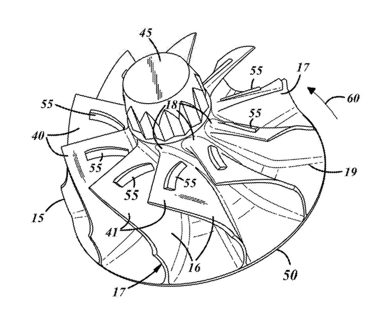
[0019]The present invention can be utilized for improving the manufacture and operation of turbine wheels and compressor wheels. The “wheels” are also known as “impellers.” The present invention will be described herein primarily with respect to turbine wheels for turbochargers, but the invention can be equally used with respects to compressor wheels for turbochargers. It is also to be noted that the present invention could be utilized for turbine and compressor wheels used in applications other than turbochargers, and thus the invention is not to be limited for use only with respect to turbochargers.

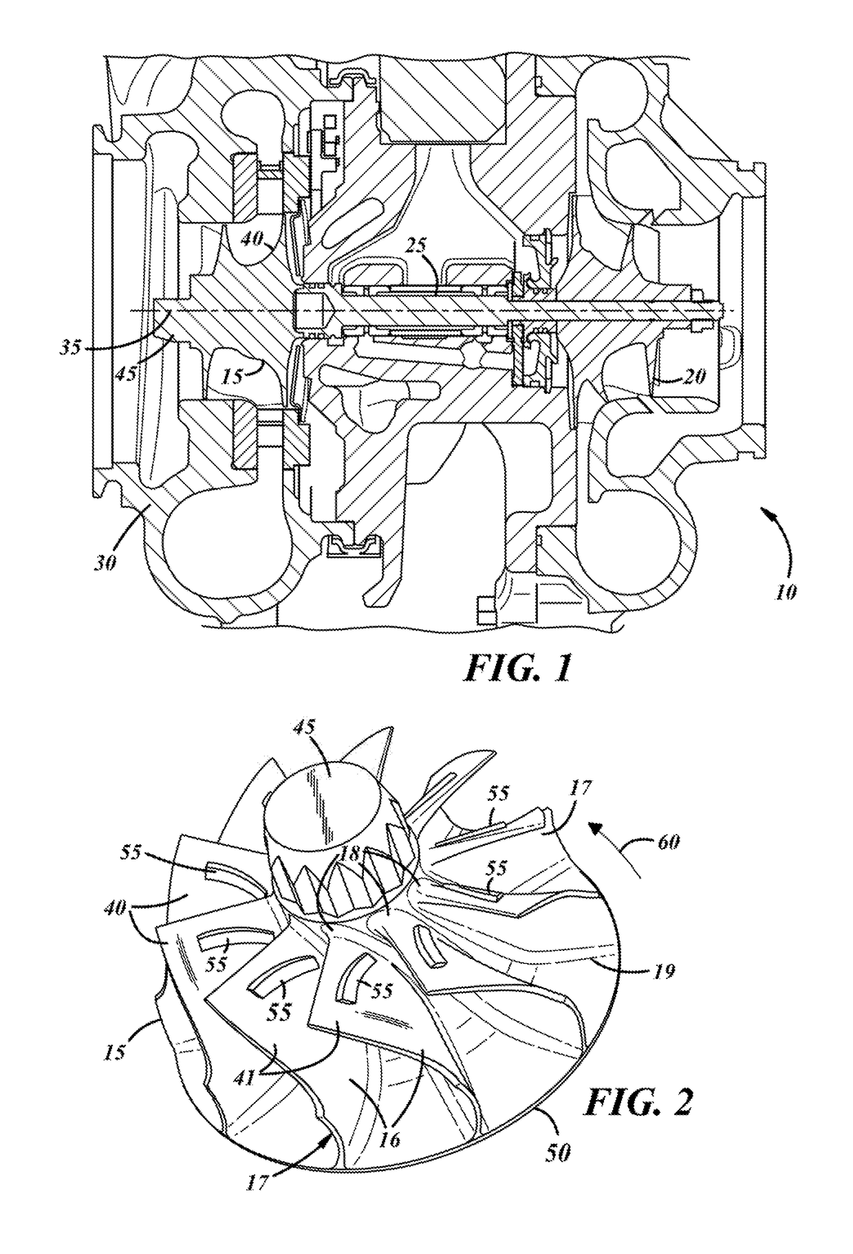
[0020]A representative turbocharger 10 is depicted in FIG. 1. The turbocharger includes a turbine wheel member 15, a compressor wheel member 20, and a shaft member 25 which connects the turbine wheel and the compressor wheel. The turbine wheel, compressor wheel and shaft are positioned in a turbocharger housing 30 and rotate around a longitudinal axis 35.

[0021]As known with turbocharger...


PUM


Abstract

A turbocharger turbine wheel member with stiffener members thereon, together with a method of manufacture therefor are disclosed. The stiffener members are molded integrally on the turbine wheel blade members. The stiffener members, as well as the manufacturing method can be utilized also for turbocharger compressor wheel members.

Description

TECHNICAL FIELD[0001]The present invention relates to turbochargers, and more particularly to improved turbine and compressor wheels for turbochargers, and methods of manufacture thereof.BACKGROUND OF THE INVENTION[0002]Turbochargers are in wide use today in automobiles and other vehicles to provide increased power and response for the vehicle engines. The turbochargers include a turbine wheel, a compressor wheel and a shaft member connecting together the two wheel members. The wheels are also called “impellers”. Exhaust gas from the engine is recirculated into the turbochargers to boost the pressure in the engine and improve performance. The compressor forces more air, and proportionally more fuel, into the combustion chamber than atmospheric pressure alone.[0003]Turbochargers are commonly used on trucks, cars, trains, aircraft and construction equipment engines. They are used most often with Otto cycle and Diesel cycle internal combustion engines.[0004]The turbine and compressor w...

Claims


Application Information

Patent Timeline
Patent Type & Authority Applications(United States)
IPC IPC(8): F01D5/04
CPCF01D5/048F05D2230/30F05D2220/40F01D5/16F05D2230/21F04D29/284F04D29/30F05D2240/126F05D2260/941
Inventor YELLAPRAGADA, LAKSHMI SRIKAR
Owner BORGWARNER INC
Features
  • Generate Ideas
  • Intellectual Property
  • Life Sciences
  • Materials
  • Tech Scout
  • Unparalleled Data Quality
  • Higher Quality Content
  • 60% Fewer Hallucinations
Learn More