Lighted waterfall device with spreading manifold

a technology of waterfall and manifold, which is applied in the field of devices for generating waterfalls, can solve the problems of difficult manufacturing and assembly of the entire device, often not completely or sufficiently lighted water itself, and often not completely or sufficiently lighted water, so as to facilitate the extension or retraction of the power cord, quick installation and replacement, and facilitate the insertion/repair/replacement of the lighting unit.

Active Publication Date: 2018-05-31
CUSTOM MOLDED PROD
View PDF0 Cites 3 Cited by
  • Summary
  • Abstract
  • Description
  • Claims
  • Application Information

AI Technical Summary

Benefits of technology

The present invention provides a waterfall device with a specialized port for easily installing and replacing a removable and replaceable lighting unit. The port has a port door and a port insertion structure that allows access to the lighting unit and electrical supply components. The port insertion structures have half-port halves that can be engaged with each other to retain and channel the power cord and any other internal components. The port insertion structures also help ensure that a unit connector end of the power cord remains within or proximate to the port and available for engagement. The lighted waterfall device also has a power cord management system and a pull-through system for easy installation and repair of the lighting unit. The technical effects of the invention include quick and easy installation of lighting units, efficient management of power cords, and improved access for repair and replacement of the lighting unit.

Problems solved by technology

The technical problem addressed in this patent is the need for a lighted waterfall apparatus that is cost-effective, easy to install and maintain, and can be permanently integrated into various structures such as spas, swimming pools, hot tubs, and garden baths. The apparatus should provide sufficient lighting to the water emanating from the waterfall, while also being simple and customizable without special skills, tools, or materials.

Method used


Image

  • Lighted waterfall device with spreading manifold
  • Lighted waterfall device with spreading manifold
  • Lighted waterfall device with spreading manifold

Examples


Embodiment Construction

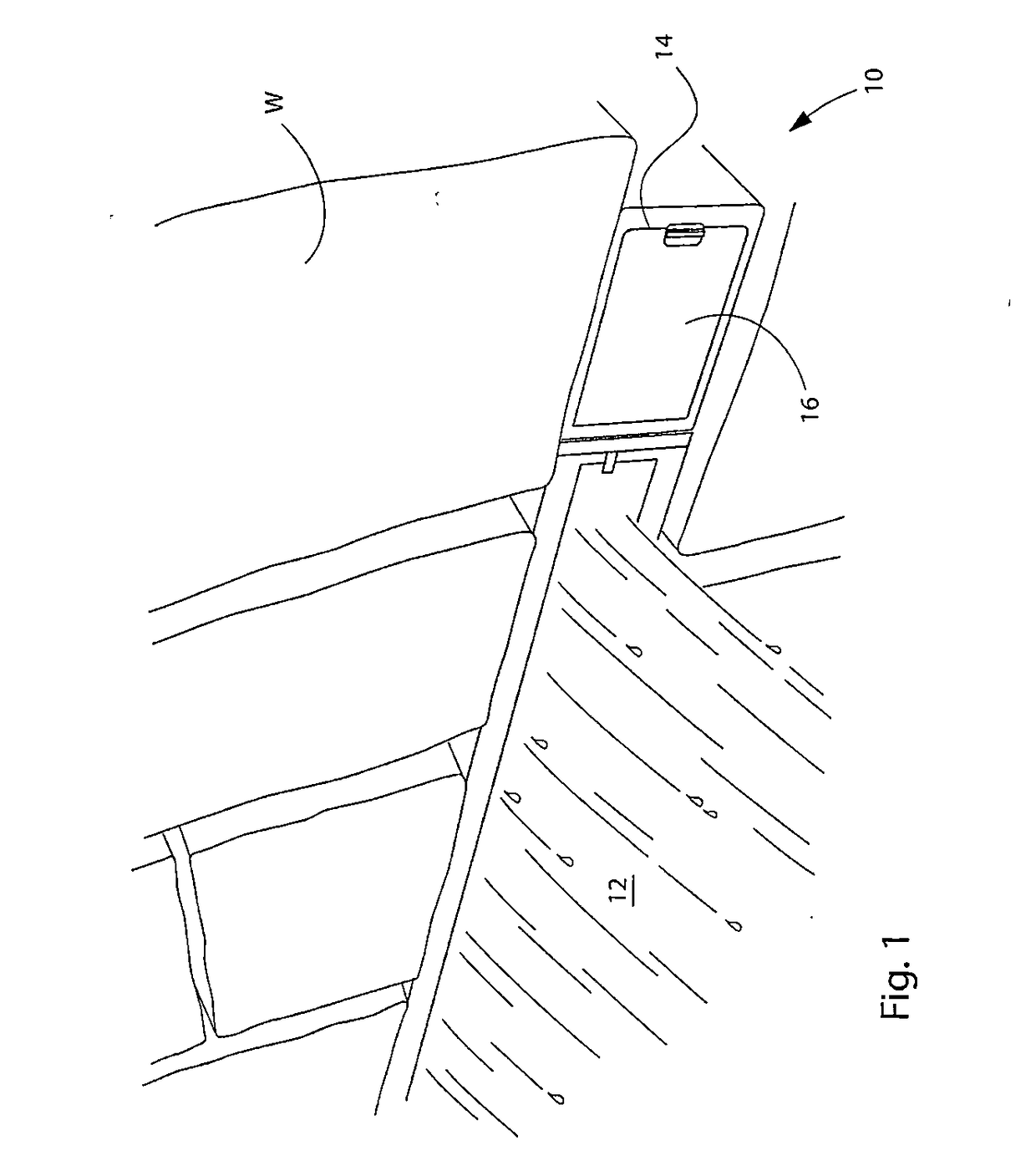
[0079]Illustrative embodiments of a first exemplary embodiment of a lighted waterfall 10 according to the present invention are shown in FIGS. 1 through 11. FIG. 1 is a top right perspective view of the inventive lighted waterfall device 10 in operation as mounted in a stone wall W and producing a waterfall 12 of water. FIG. 1 also illustrates a representative placement of a first exemplary embodiment of a port 14 and port door 16, which is a means for accessing the means for lighting 18 the waterfall 12.

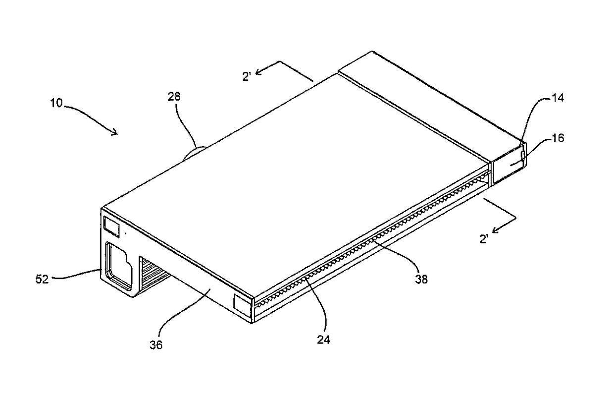
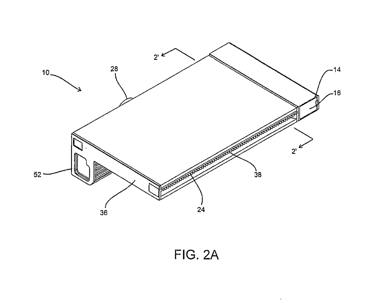
[0080]FIG. 2A is a top left perspective view of the lighted waterfall device 10 and FIG. 2B is a left perspective cross section view of the lighted waterfall device 10 through line 2′-2′ of FIG. 2A. FIG. 2C is a right perspective view of the lighted waterfall device 10 showing a detail of a portion of the interior of the lighted waterfall device 10.

[0081]FIG. 3A is a left plan view and FIG. 3B is a left perspective view of the lighted waterfall device 10. FIG. 3C is a left perspecti...


PUM


Abstract

A low profile, lighted waterfall apparatus for producing a sufficiently lit artificial waterfall having a light source chamber, distal to a waterfall slot/primary outlet and substantially aligned on the same plane therewith, and a port for accessing the light source, such that the light source can be easily accessed, inserted, removed, and/or replaced. The light source chamber having a transparent, semi-transparent, or translucent divider to shine light towards and across the waterfall slot/primary opening via a spreading manifold/area/passage that is configured to spread the flowing water, and direct the water as a fluid wave guide towards the waterfall slot/primary outlet.

Description


Claims


Application Information

Patent Timeline
Owner CUSTOM MOLDED PROD
Why Eureka
Try Eureka