Automatic spent magazine ejection & control group

Active Publication Date: 2018-05-31
9579087 CANADA INC
View PDF0 Cites 17 Cited by
  • Summary
  • Abstract
  • Description
  • Claims
  • Application Information

AI Technical Summary

Benefits of technology

[0032]The charging handle of the present invention is less susceptible to getting caught on objects, such clothing or straps, and to getting damaged because the grip wings are folded inwards when the charging handle is not in use.
[0033]The charging handle of the p

Problems solved by technology

Unfortunately, the process of replacing an empty magazine with a loaded magazine requires multiple steps and is time consuming.
In the many different critical and dangerous situations which can be faced by users in the military, law enforcement, security and even hunting, time is limited.
Charging handles often protrude out one side of the firearm and are therefore, susceptible to getting caught on objects and getting damaged.
Furthermore, many charging handles are not sufficiently large or easy to grip by users, such as users who are wearing gloves or protective clothing.
Most users are not ambidextrous and therefore, will generally find it more difficult to operate a control present on only one of the two sides of the firearm.
Alternatively, in critical and dangerous situations which can be faced by a user, the user's

Method used


Image

  • Automatic spent magazine ejection & control group
  • Automatic spent magazine ejection & control group
  • Automatic spent magazine ejection & control group

Examples


Example

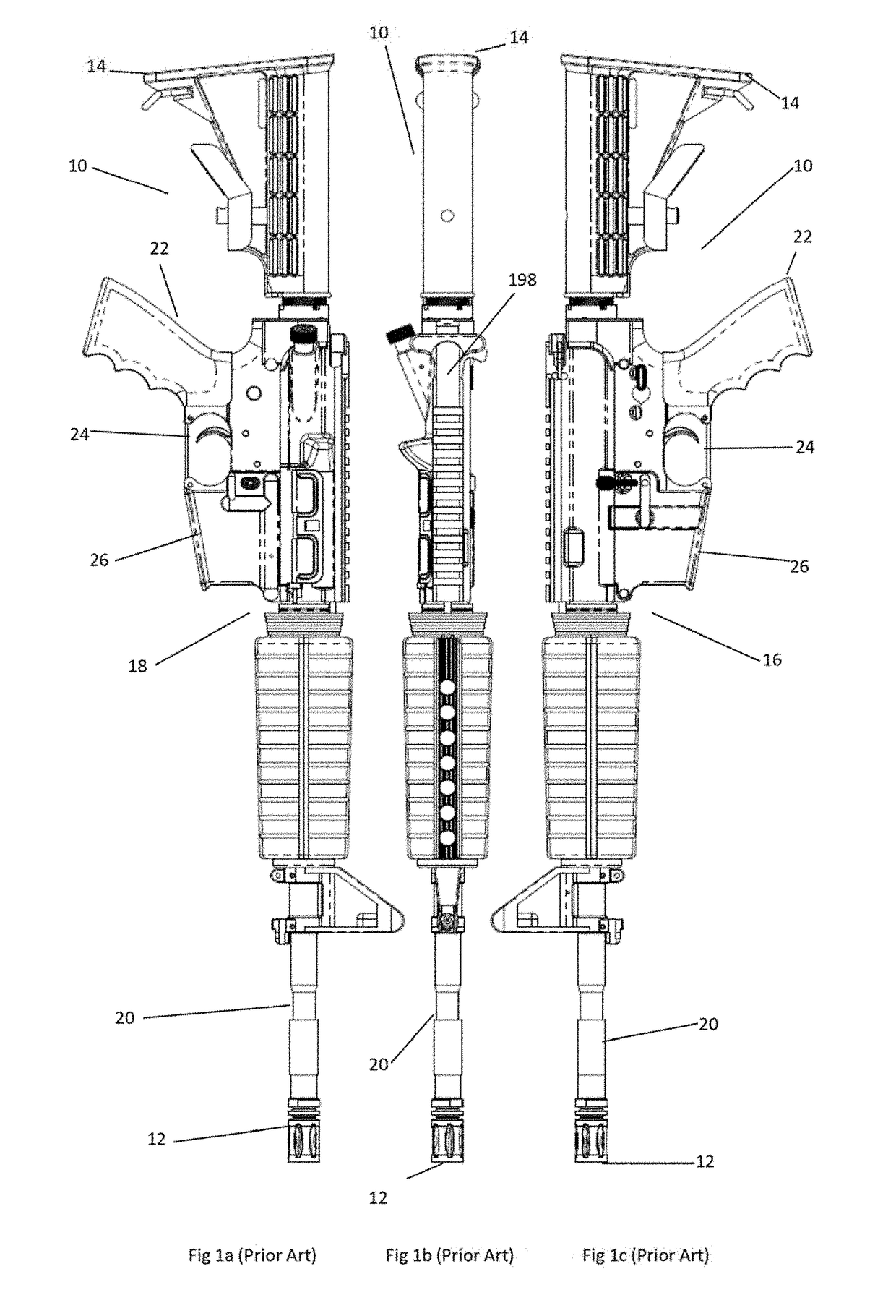
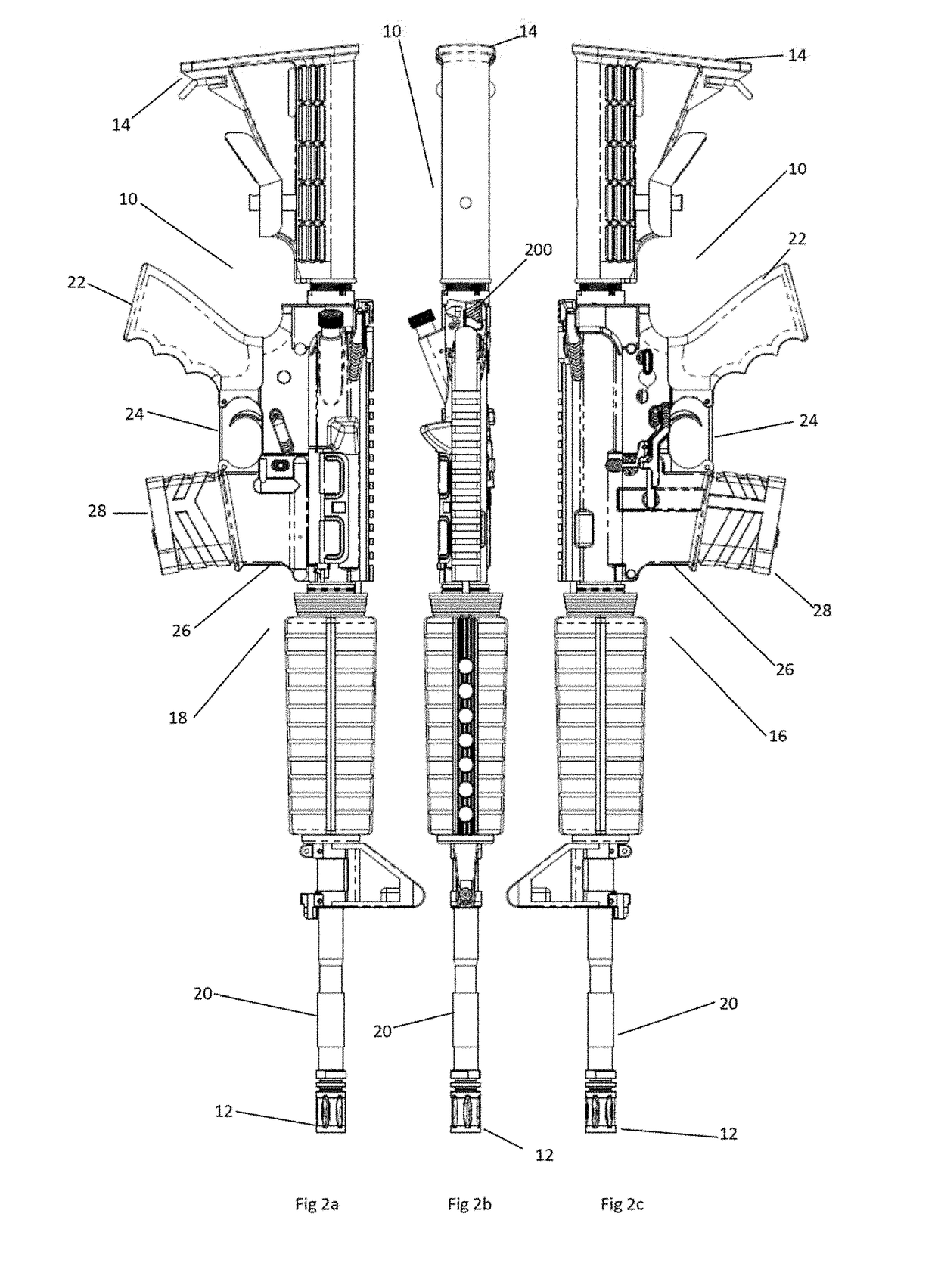
[0053]A preferred embodiment of the firearm 10 of the present invention is illustrated in FIGS. 2 to 5, and can be compared to the prior art AR-15 rifle shown in FIG. 1. Firearm 10 has a forward end 12 and a rearward end 14. The firearm 10 also has a left side 16 and a right side 18. The forward end 12 includes the barrel 20 from which a projectile, such as a bullet, is launched towards a target. The length and diameter of the barrel 20 varies widely depending on the type of firearm. The rearward end 14 includes a handle 22 onto which a user grips the firearm 10. A trigger 24 is present forward of the handle 22 and is squeezed rearwards by the user when the user desires to fire a bullet.

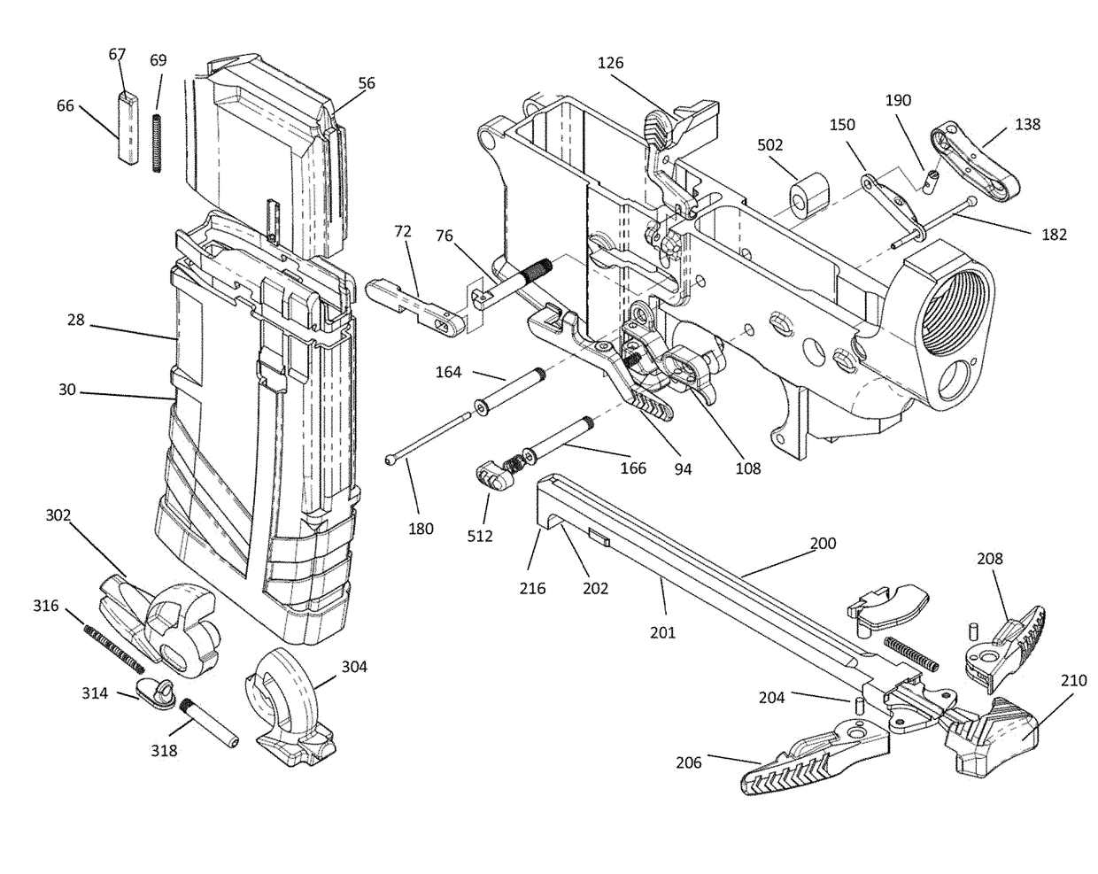
[0054]A lower receiver 26 is present between the barrel 20 and trigger 24, wherein the lower receiver 26 is the point of attachment for an ammunition magazine 28. FIGS. 6 to 9 illustrate a preferred embodiment of the ammunition magazine 28 of the present invention. The magazine 28 includes a containe...


PUM


Abstract

A firearm comprising: (i) an ammunition magazine which automatically ejects from the lower receiver of the firearm when the ammunition magazine is spent; (ii) a control group comprising a magazine release mechanism for releasing the magazine catch so that the ammunition magazine is detachable from the lower receiver, a bolt catch engage mechanism for engaging the bolt catch with the bolt carrier and retaining the bolt carrier in the retracted position, and a bolt catch release mechanism for releasing the bolt catch from the bolt carrier and allowing the bolt carrier to move forward, wherein the control group components can be operated by the user on either the left side or right side of the firearm; and (iii) optionally, a charging handle which can be operated by the user on either the left side or right side of the firearm.

Description

CROSS REFERENCING OF RELATED APPLICATIONS[0001]This application claims priority to and is a national phase under 37 CFR 1.371 of International Patent Application No. PCT / IB16 / 052810, filed on May 16, 2016, entitled “Automatic Spent Magazine Ejection & Control Group”, which claims priority to U.S. Patent Application No. 62 / 168,714, filed on May 29, 2015, entitled “Automatic Spent Magazine Ejection & Control Group” and, both of which are incorporated by reference herein in their entirety.FIELD OF THE INVENTION[0002]The present invention relates to firearms, and more particularly, to firearms that operate using ammunition magazines and bolt systems.BACKGROUND[0003]Firearms are commonly used in industries such as the military, law enforcement, security, hunting and recreational target shooting. Many of today's firearms operate through the coordinated actions of an ammunition magazine and a bolt carrier.[0004]Ammunition magazines store and feed multiple cartridges of ammunition while wit...

Claims


Application Information

Patent Timeline
IPC IPC(8): F41A9/59F41A9/65F41A17/38
CPCF41A9/59F41A9/65F41A17/38F41A17/36F41A3/72F41A35/06
Inventor HEADRICK, DAVID ARTHURMACHADO, LEONEL HENRIQUES
Owner 9579087 CANADA INC
Why Eureka
Try Eureka