Connector

a technology of connecting rods and connectors, applied in the direction of coupling contact members, fixed connections, coupling device connections, etc., can solve the problems of only being used for connectors and the structure of connectors becomes more complex, and achieve the effect of simple configuration and reliably supporting a connection

Active Publication Date: 2018-05-31
MOLEX INC
View PDF0 Cites 1 Cited by
  • Summary
  • Abstract
  • Description
  • Claims
  • Application Information

AI Technical Summary

Benefits of technology

[0015]According to the present disclosure, even a small connector with a simple configuration can reliably sustain a connection between a substrate connecting portion of a terminal and a connecting pad of a substrate.

Problems solved by technology

However, because the substrate 891 is being sandwiched from above and below by the upper case 811 and the lower case 841 in the conventional connector, the structure of the connector becomes more complex as the connector becomes larger.
Furthermore, the connector can only be used in an environment where there is a space below the substrate 891 large enough to house the lower case 841.

Method used


Image

  • Connector
  • Connector
  • Connector

Examples


Embodiment Construction

[0031]The embodiments will be described in detail below with reference to the drawings.

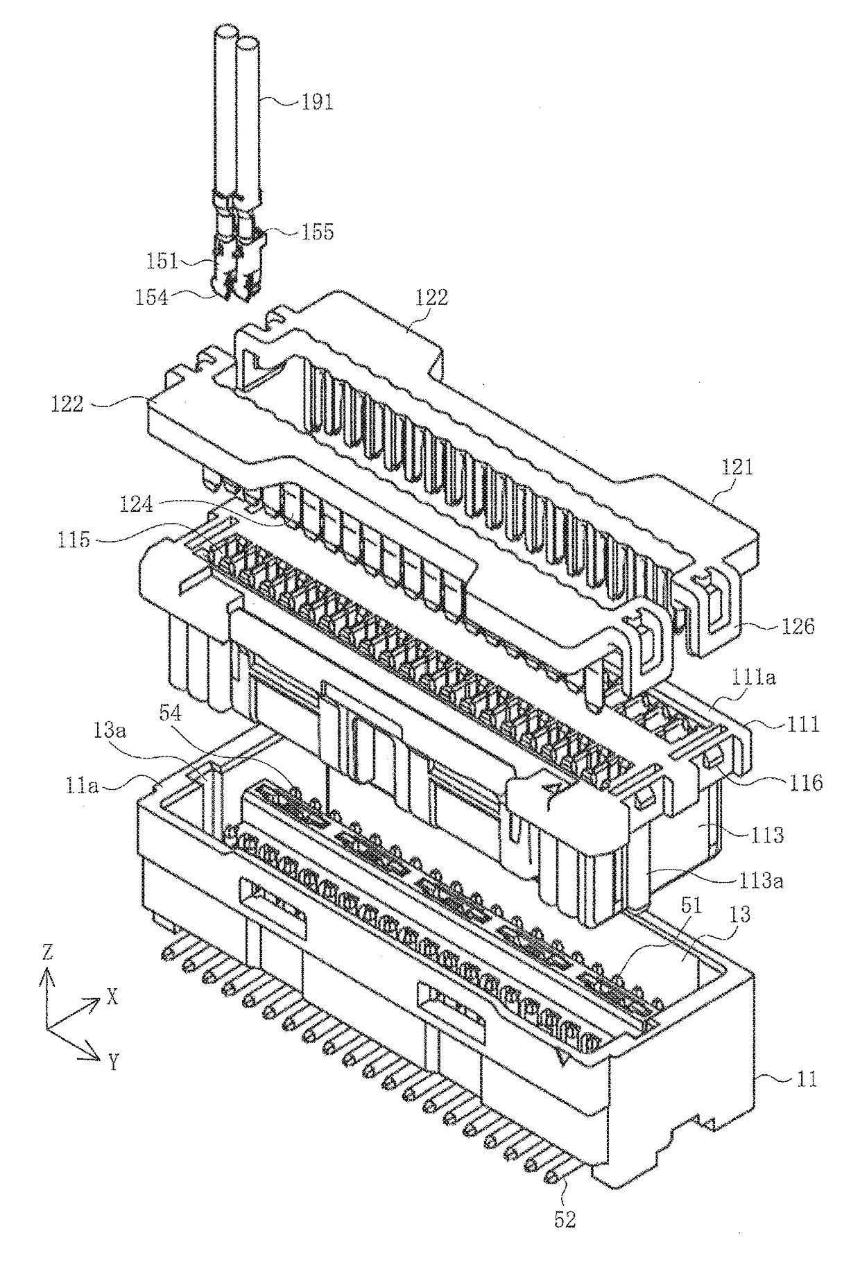
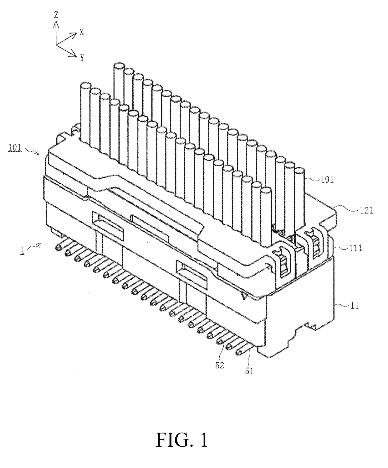
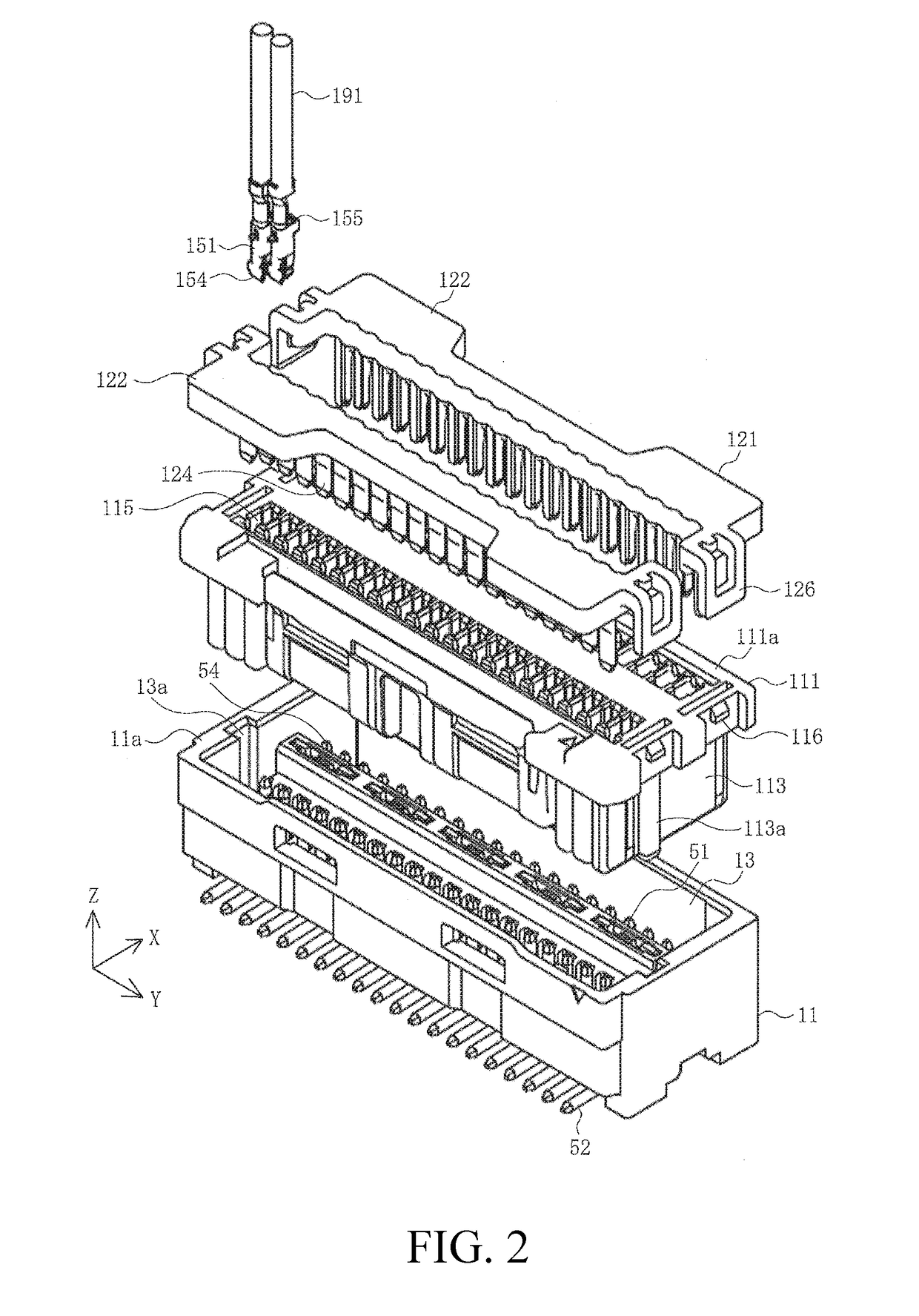
[0032]FIG. 1 is a perspective view illustrating a state where a substrate connector is fitted with a wire connector in a first embodiment, and FIG. 2 is an exploded view of the wire connector in a state prior to being fitted with the substrate connector in the first embodiment.

[0033]In the figures, 1 is a substrate connector that serves as a connector in the present embodiment, and is a connector that mounts to a surface 91a of a substrate 91 of a circuit board, and the like, to be described later. Furthermore, 101 is a wire connector that serves as a counterpart connector in the present embodiment, and is a connector that connects to termini of a plurality of wires 191. The substrate connector 1 and the wire connector 101 may be used in a variety of applications, and thus are used in a variety of equipment, such as a variety of electronic equipment, household equipment, medical equipment, industr...


PUM


Abstract

A connector is provided that has a terminal, a housing for retaining the terminal, and a reinforcing bracket retained in the housing. The housing includes a fitting concave portion that fits with a counterpart connector and a bottom plate portion that faces a surface of a substrate. The terminal includes a contact portion that makes contact with a counterpart terminal of the counterpart connector inside the fitting concave portion and a substrate connecting portion exposed from a lower surface of the bottom plate portion and connected to a connecting pad on the surface of the substrate. The reinforcing bracket includes a main body portion retained in the housing inside the fitting concave portion and a leg portion exposed from the lower surface of the bottom plate portion and connected to the connecting pad on the surface of the substrate.

Description

RELATED APPLICATIONS[0001]This application claims priority to U.S. Patent Application No. 62 / 426,868, filed Nov. 28, 2016 and Japanese Application No. 2017-082968, filed Apr. 19, 2017, both of which are incorporated herein by reference in their entireties.TECHNICAL FIELD[0002]The present disclosure relates to a connector.BACKGROUND ART[0003]Conventionally, in a connector mounted on a substrate, such as a circuit board, and the like, a connector case sandwiches the connector from both sides to prevent the application of large loads on solder used to secure and connect a terminal to the substrate when external force, and the like, is received (for example, see Patent Document 1).[0004]FIG. 15 is a perspective view illustrating a conventional connector.[0005]In the figure, 811 is a connector upper case, and 841 is a connector lower case. A fitting concave portion 813 into which a counterpart connector not illustrated in the figure fits is formed in the upper case 811, and a plurality o...

Claims


Application Information

Patent Timeline
Patent Type & Authority Applications(United States)
IPC IPC(8): H01R12/71H01R13/436H01R12/70H01R12/72H01R12/52H01R13/26
CPCH01R12/716H01R13/4361H01R12/707H01R12/724H01R12/52H01R13/26H01R13/4223H05K2201/10189H05K3/368H01R12/57H01R12/7052H01R13/02H01R13/502H01R13/73H01R13/41H01R13/5219
Inventor CHIKANO, KOJIIKEDA, MAKIKOASAKAWA, KAZUSHIGE
Owner MOLEX INC
Why Eureka
Try Eureka