Transfer and locomotion apparatus

Active Publication Date: 2012-05-31
TMSUK CO LTD
View PDF16 Cites 11 Cited by
  • Summary
  • Abstract
  • Description
  • Claims
  • Application Information

AI Technical Summary

Benefits of technology

[0072]As described above, the transfer and locomotion apparatus according to the present invention can provide the following advantages.
[0073]The invention recited in the first aspect provides the following advantage.
[0074]The invention recited in the second aspect provides the following advantage, in addition to the advantage of the first aspect.
[0075]The invention rec

Problems solved by technology

It is difficult for a person who does not have the strong muscle of the upper extremity to improve the skill of operating a standard wheelchair.
When the caretaker gets the disabled person around the caretaker's arm to sustain the disabled person's weight, a significant burden is applied to the caretaker, and therefore the caretaker is likely to suffer from lumbar pain.
In addition, a general wheelchair lacks usability, because there is a risk that the user loses the balance and falls down when getting on and off the wheelchair.
In particular, a spine-injured patient who feels no pain due to the injured-spine cannot perceive physical pain, and therefore is likely to suffer from the blood circulation disorder.
Meanwhile, in a case of using a lifter, it takes a lot of trouble to prepare for suspending a person requiring nursing care, and therefore the caretaker has a bigger burden.
In addition to this, large space is required to pla

Method used


Image

  • Transfer and locomotion apparatus
  • Transfer and locomotion apparatus
  • Transfer and locomotion apparatus

Examples


embodiment 1

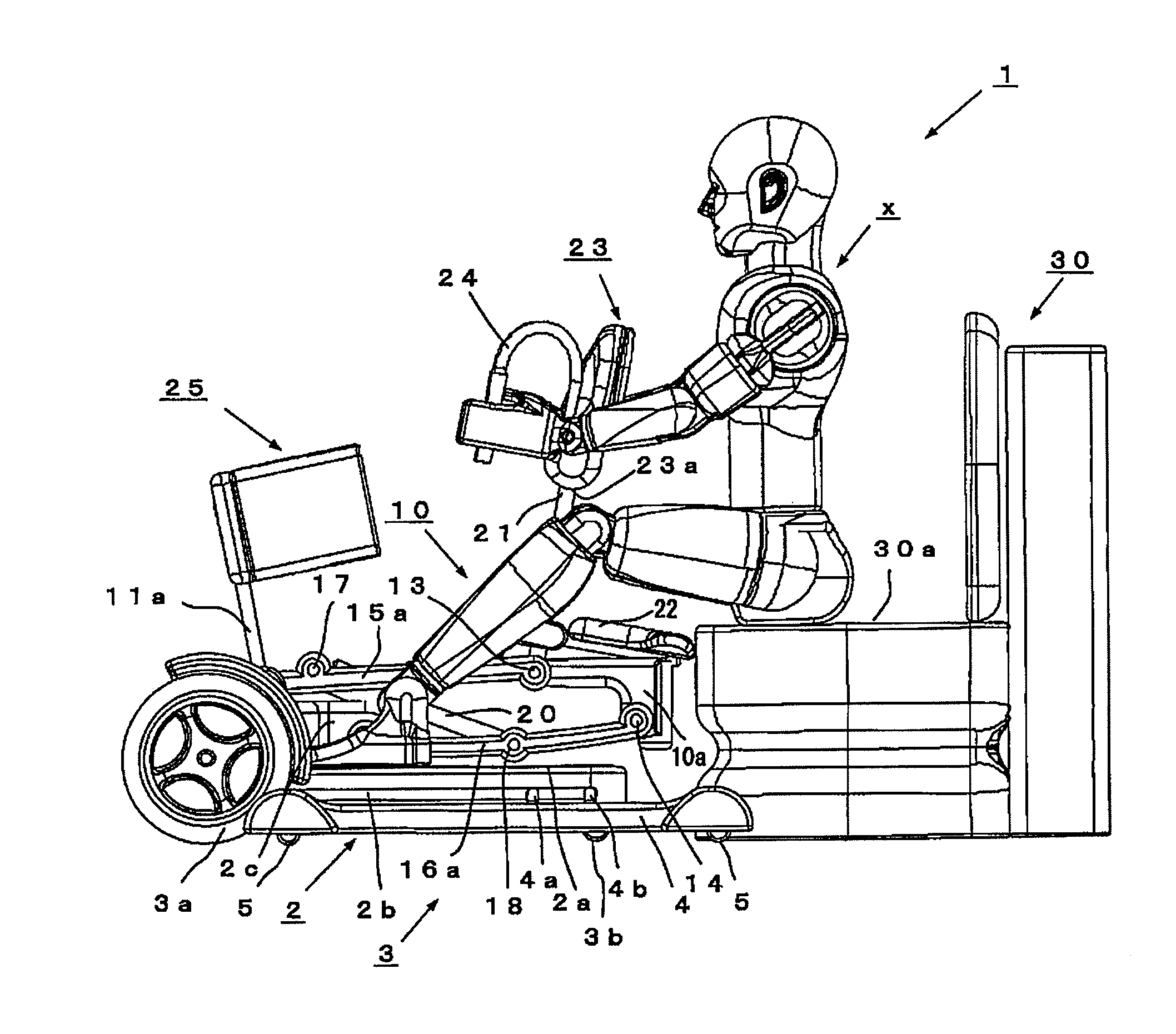
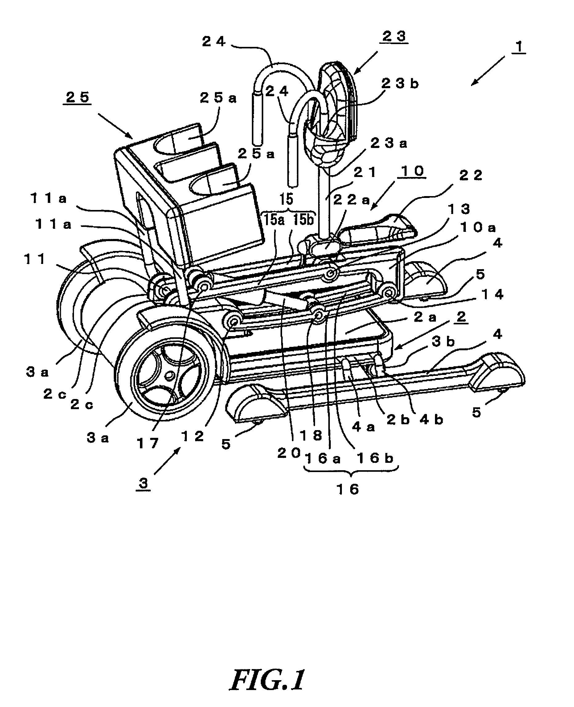
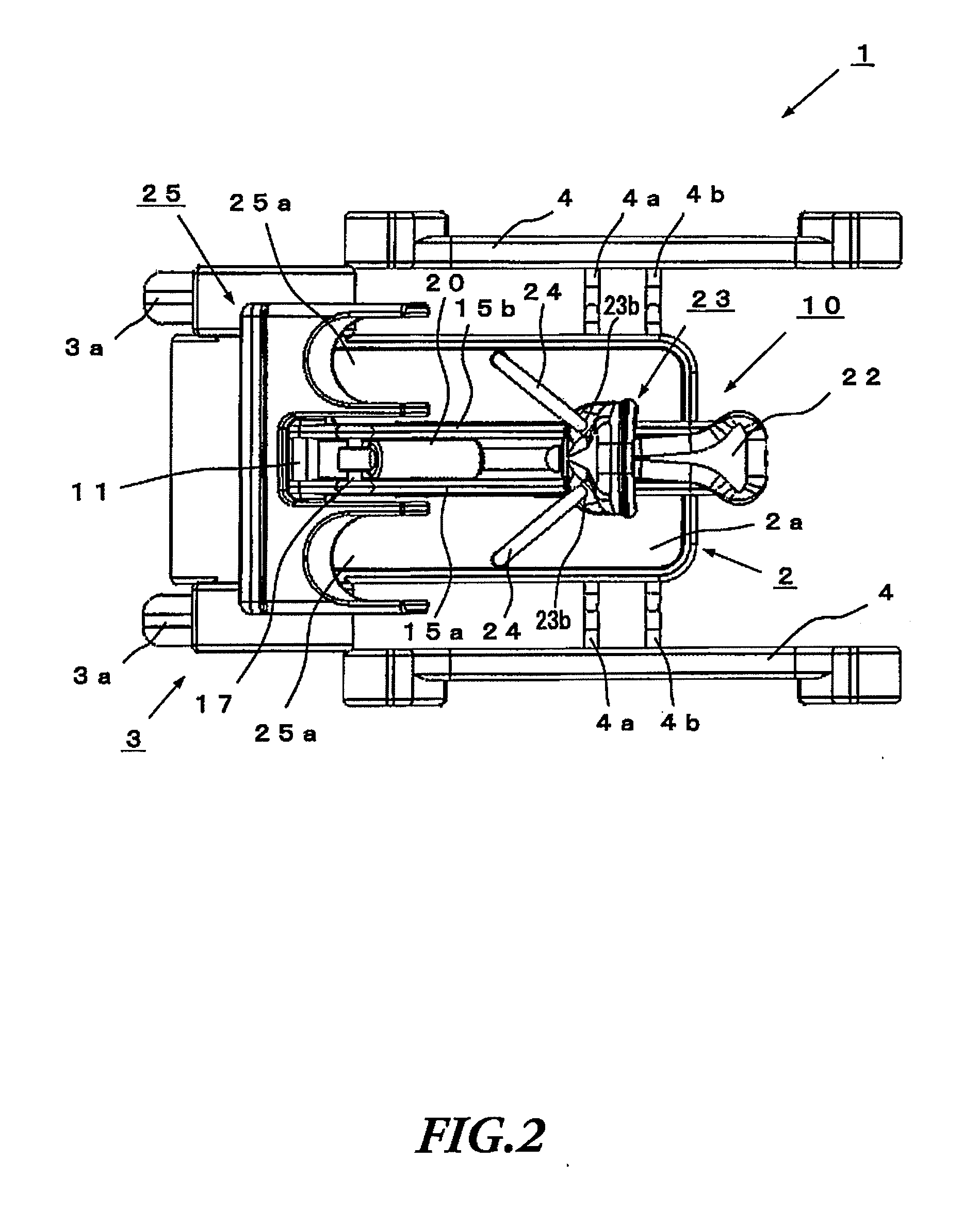
[0094]FIG. 1 is a perspective view schematically showing a state in which a seat part of a transfer and locomotion apparatus according to Embodiment 1 is lowered. FIG. 2 is a plan view schematically showing a state in which the seat part of the transfer and locomotion apparatus according to Embodiment 1 is lowered. FIG. 3 is a side view schematically showing a state in which the seat part of the transfer and locomotion apparatus according to Embodiment 1 is lowered.

[0095]In FIG. 1 to FIG. 3, reference numeral 1 denotes a transfer and locomotion apparatus according to Embodiment 1 of the present invention, 2 denotes a base part of the transfer and locomotion apparatus 1 parallel to the ground, 2a denotes an upper surface of the base part 2, 2b denotes a guide slit opening on both side surfaces of the base part 2, 2c denotes left and right pivot shaft holding plates standing on the front portion of the base part 2, 3 denotes a driving part for the base part 2, which has driving wheels...

embodiment 2

[0127]FIG. 9 is a side view schematically showing a state where the seat part of the transfer and locomotion apparatus according to Embodiment 2 is lowered.

[0128]In FIG. 9, a transfer and locomotion apparatus 1A according to Embodiment 2 is different from the transfer and locomotion apparatus 1 according to Embodiment 1 in that a drive mechanism part 10A is employed to move the seat part 22 and the breast pad part 23 upward and downward using a piston cylinder 20A, which may be a hydraulic or gas-pressure cylinder, instead of the drive mechanism part 10 using the four-link mechanism to allow the seat part 22 and the breast pad part 23 to pivotably rotate and move upward and downward; in that the pivot shaft holding part 10b is integrally formed with the lower portion of the seat part 22; and in that the strut 21 is pivotably held by the pivot shaft holding part 10b via the coupling pivot shaft 13a.

[0129]Although, with the present embodiment, the piston cylinder 20A is employed in t...

embodiment 3

[0133]FIG. 10 is a plan view schematically showing a state where the seat part of the transfer and locomotion apparatus according to Embodiment 3 is lowered. FIG. 11 is a side view schematically showing a state where the user rides on the transfer and locomotion apparatus according to Embodiment 3 in a standing posture. FIG. 12 is a side view schematically showing a state before the user transfers to a toilet seat using the transfer and locomotion apparatus according to Embodiment 3.

[0134]Through FIG. 10 to FIG. 12, a transfer and locomotion apparatus 1B according to Embodiment 3 is different from the transfer and locomotion apparatus 1 according to Embodiment 1 in that a driving wheel 3a of the driving part 3 is smaller; in that a footrest part 2d is provided on the upper surface 2a of the base part 2 to slidably move forward and backward; and in that a waist pad part 22c is provided, which is pivotably held in the rear end portion of the seat part 22.

[0135]In FIG. 10, the footrest...


PUM


Abstract

Disclosed is a transfer and locomotion apparatus with excellent functionality, stability, versatility, and user-friendliness such that a person requiring nursing care can transfer between the transfer and locomotion apparatus to a bed and a toilet seat, etc., keeping the orientation of the body. The apparatus has a simple structure, is operable by a single person, imposes no strain on the person's back and lumbar part, etc., and can comfortably be used even if the person has injured-spine and so forth. The apparatus comprises a base part having a driving part, a seat part provided on the base part and which a user can sit from a back portion or a side portion, and a breast pad part standing in a front end side of the seat part and contacting a breast of the user. At least one of the seat part and the breast pad part is held to be able to move forward and backward, and upward and downward with respect to the base part.

Description

TECHNICAL FIELD[0001]The present invention relates to a general-purpose transfer and locomotion apparatus. The transfer and locomotion apparatus according to the present invention can be easily used to locomote by not only people having no disabilities, but also people requiring nursing care, such as old people getting weak legs and physically handicapped people. Even if used for a long period of time, the transfer and locomotion apparatus does not impose a strain on the back and the lumbar part of the user, and, particularly, even if the user has injured-spine, the transfer and locomotion apparatus can be used comfortably. Moreover, it is easy for the user to transfer from the transfer and locomotion apparatus to a bed, a toilet seat, a wheelchair and so forth.BACKGROUND ART[0002]Conventionally, a wheelchair has generally been used by a person who cannot walk even by using a stick due to the paralysis of the lower extremities. Such a person can locomote, operating this wheelchair h...

Claims


Application Information

Patent Timeline
IPC IPC(8): A61G5/10
CPCA61G5/042A61G5/14A61G7/1007A61G7/1048A61G7/1086A61G5/12A61G2005/124A61G2005/127A61G2200/34A61G2200/36A61G2200/56A61G7/109A61G5/124A61G5/127
Inventor TAKAMOTO, YOICHIKAWAKUBO, YUJIMIYAMOTO, KENICHIBBA, KATSUYUKITAKASUGI, SHIN-ICHIROKUSABA, RYUICHIIWAMOTO, YUKIHIDE
Owner TMSUK CO LTD
Why Eureka
Try Eureka