

Assembly well irrigation system for environmentally friendly water conservation
- Summary
- Abstract
- Description
- Claims
- Application Information
AI Technical Summary
Benefits of technology
Problems solved by technology
Method used
Image

Examples
Embodiment Construction
[0031]The above and other objects, features and advantages of this disclosure will become apparent from the following detailed description taken with the accompanying drawings.
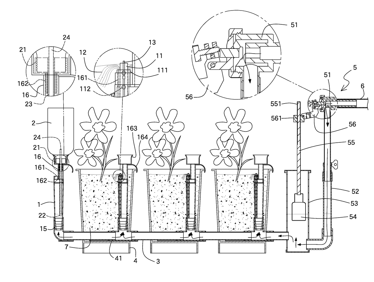
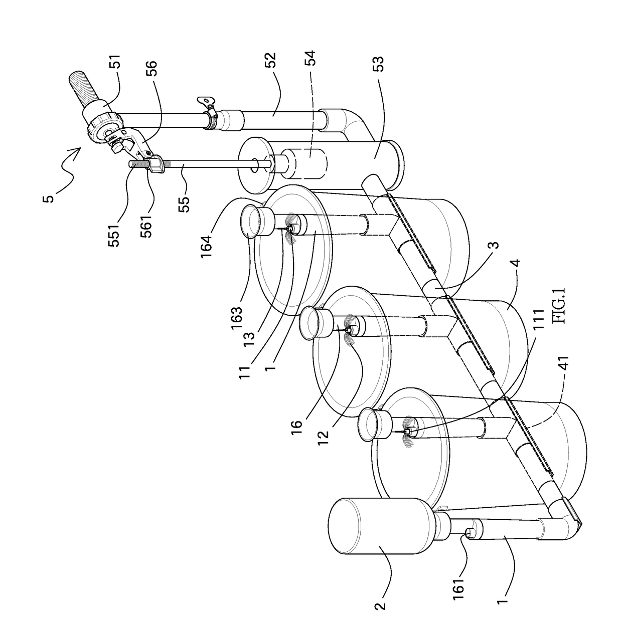
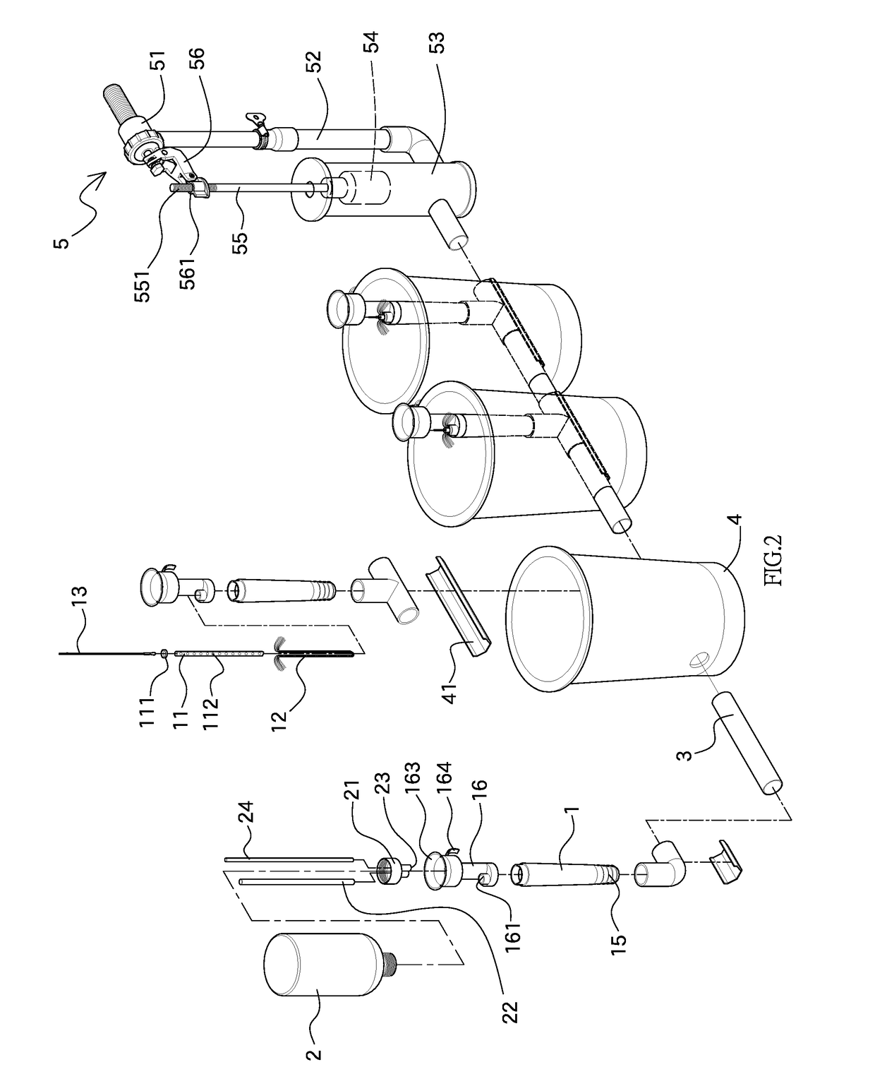
[0032]With reference to FIGS. 1 to 5 for an assembly well irrigation system for environmentally friendly water conservation in accordance with the first embodiment of the present invention, the assembly well irrigation system comprises the following parts:
[0033]As shown in FIG. 2, the irrigation system comprises at least one well 1 with a ventilation tube 11 inserted into the well 1, and an absorbent element 12 covered onto the bottom and outer wall of the ventilation tube 11 and filled up in an opening between the top of the well 1 and the ventilation tube 11. To save the absorbent element 12 and its installation cost, the absorbent elements 12 are installed linearly, and both ends of the absorbent element 12 are protruded from the well 1. To further improve the penetration force of the absorbent element 12, ...
PUM
 Abstract
Description
Claims
Application Information